- 10 -
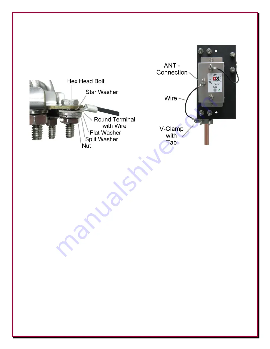
Install the ground wire hardware and ground wire on the stainless steel V-Clamp with the tab. The other end of this
wire goes to the
AVA-2
ANT-
connection as shown in
Figure 6
.
Страница 1: ...r Vertical Array Package ARAV3 8P Eight Vertical Array Package Export Models ARAV3 1PE ARAV3 2PE ARAV3 4PE ARAV3 8PE Used under US Patent No 7 423 588 DXE ARAV3 INS Revision 4a DX Engineering 2012 P O...
Страница 2: ...ription 6 Basic Tools Required 7 Installation 7 Location 7 Assembly 7 Ground Mounting Rod 9 Three Piece 102 Receiving Element WP 102E 11 Providing a Good RF Ground 12 Connections 12 Coaxial Cable Feed...
Страница 3: ...e using two ARAV3 antennas in conjunction with the DXE NCC 1 Receive Antenna Variable Phasing Controller could allow the user to phase out the noise being received Large transmit antennas are a very g...
Страница 4: ...nsmit antennas is at least 1 10 wavelength or more Ideally your receive antenna should be a minimum of 1 2 wavelength away from any transmit antenna on the lowest frequency to avoid mutual coupling an...
Страница 5: ...systems w Internal Antenna Disconnect Relays 4 Element connection wires 4 Sets of Stainless steel clamps and hardware DXE ARAV3 8P The eight active antennas system package DXE ARAV3 8P is intended fo...
Страница 6: ...ting plate and stainless steel U Bolt Saddle clamps for mounting to your 4 foot ground rod May be connected to a transceiver which lacks a receive antenna input using the optional DXE RTR 1A Receive A...
Страница 7: ...tructures becomes more pronounced At higher frequencies where the active element length becomes a partial wavelength coupling increases further Placing a DXE ARAV3 on the same mast or tower as a Yagi...
Страница 8: ...n Figure 3 Figure 3 Upper Clamp Lower Clamp NOTE The following describes the use of the DXE SSVC 1P and DXE SSVC 1PG V Clamps that are included with the ARAV3 These are used for mounting the ARAV3 on...
Страница 9: ...Drive your four foot copper clad steel ground rod into the ground far enough to provide a sturdy mount for the antenna system Ensure the ARAV3 unit will be above any potential standing water Depending...
Страница 10: ...10 Install the ground wire hardware and ground wire on the stainless steel V Clamp with the tab The other end of this wire goes to the AVA 2 ANT connection as shown in Figure 6 Figure 6...
Страница 11: ...ions together The other connector has smaller holes for joining the middle to the upper section Lower Coupler Upper Coupler Stripe Lower Section Middle Section Upper Section Figure 7 Three Section Sta...
Страница 12: ...re not recommended for transmit antennas Screen radius must at least equal the element height and be placed around the antenna as symmetrically as possible but should not exceed a radius of 20 feet Th...
Страница 13: ...ding on the number of control lines needed usually 3 or 4 you can double up the twisted pairs of CAT5e cable or use control wire that is at least 22 AWG allowing runs up to 1500 feet If you use a cabl...
Страница 14: ...r nicks displaces water and can be direct buried The feedline is used to provide power for the ARAV3 s matching unit We recommend the use of DXE SNS6 25 Snap N Seal type F connectors to ensure high qu...
Страница 15: ...ove the peak frequency does not change significantly Below the peak frequency sensitivity reduction is reasonably fast Installing a jumper in any C1 position when jumpers are being used in L1 will mov...
Страница 16: ...3 units are used in a four square array optimized for 160 meters and 80 meters with 98 feet side lengths the only jumper typically used is L1MF Configure all four ARAV3 s units in the array with the s...
Страница 17: ...1P Active Receive Vertical antenna capabilities Normally the Active Receive Vertical antenna will properly reject high angle sky wave signals which is the goal for a low band DXing receive antenna Low...
Страница 18: ...antenna feedline that is running on or above ground or similar noise as your transmit antenna for some installations the DXE RFCC 1 Receive Feedline Current Choke may help The use of the DXE RFCC 1 Re...
Страница 19: ...19 Shortwave Receiver ARAV3 1P system located greater than 1 2 wavelength from any transmitting antenna connected to a transceiver with a receive input...
Страница 20: ...preferably more than 1 2 wavelength away The NCC 1 switches the power off during transmit This configuration allows the operator to selectively null out interference and thereby enhance the desired re...
Страница 21: ...21 Typical DXE RFS SYS 4P Receive Four Square System Configuration Shown with optional items Power connections not shown for clarity Refer to the DXE RFS SYS 4P manual for details...
Страница 22: ...22 Typical DXE RCA8 SYS 4P Receive Eight Circle System Configuration Shown with optional items Power connections not shown for clarity Refer to the DXE RCA8 SYS 4P manual for details...
Страница 23: ...ity 360 brass cadmium plated with yellow chromate coating for maximum corrosion resistance UV resistant plastic and O rings provide a reliable environmentally sealed connector An installation tool suc...
Страница 24: ...dit repair or replace any item or part thereof which is proved to be other than as warranted no allowance shall be made for any labor charges of Buyer for replacement of parts adjustment or repairs or...