


5.0 MAINTENANCE
The Positioner requires no routine maintenance. It is highly recommended that quality instrument air be
used as described in section 2.2.2 Instrument Air Requirements.
The restriction and filter screens may require periodic cleaning. The frequency of their cleaning is con-
ditional depending on the quality of instrument air used.
In the unlikely even the 150N Series Positioner should fail, the unit can be returned to the factory for
warranty repair if the warranty period has not expired. All units returned for repair are to be shipped
freight prepaid to:
Dwyer Instruments, Inc.
Jct. IN 212 and US 12
Michigan City, IN 46360
Attention: Repair Department
5.1 RESTRICTION
The restriction is cleaned with the cleaning wire which is attached to the holding screw for the housing
cover. See Figure 2-3 for cleaning wire location.
1. Turn off air supply.
2. Unscrew and remove cleaning sire and restriction sealing screw.
3. Run cleaning wire through restriction in pilot ring several times.
4. Reinstall restriction sealing screw and cleaning wire.
5.2 FILTER SCREENS
Filter screens are located in the V1, V2, and supply ports. A screen must be removed from the spool
housing to be cleaned. Screens can be damaged during removal; have spare screens on hand. Refer
to the Parts List at the back of this Instruction.
1. Turn air supply off.
2. Remove a screen with a scribe by carefully pulling on and around the edge of a screen.
3. Clean a screen by blowing through in the reverse direction with compressed air. Soak a screen in
solvent or clean mechanically if necessary.
4. Insert a screen until it bottoms using an object, such as the eraser end of a pencil, that will not
cause damage.
W.E. ANDERSON DIV., DWYER INSTRUMENTS, INC.
P.O. BOX 358 • MICHIGAN CITY, INDIANA 46361 U.S.A.
Phone: 219/879-8000
www.dwyer-inst.com
Fax: 219/872-9057
e-mail: [email protected]
PAGE 22
BULLETIN F-56
Bulletin F-56 6/27/05 9:37 AM Page 22
Содержание W.E. Anderson 150N Series
Страница 7: ...BULLETIN F 56 PAGE 7 FIGURE 2 1 Cam and Associated Hardware Bulletin F 56 6 27 05 9 37 AM Page 7...
Страница 13: ...BULLETIN F 56 PAGE 13 FIGURE 2 3 Standard Cam Characteristics Bulletin F 56 6 27 05 9 37 AM Page 13...
Страница 14: ...PAGE 14 BULLETIN F 56 FIGURE 2 4 Cam Installation A Side Example Bulletin F 56 6 27 05 9 37 AM Page 14...
Страница 15: ...BULLETIN F 56 PAGE 15 FIGURE 2 5 Cam Installation B Side Example Bulletin F 56 6 27 05 9 37 AM Page 15...
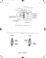
Страница 17: ...BULLETIN F 56 PAGE 17 FIGURE 3 1 Calibration Bulletin F 56 6 27 05 9 37 AM Page 17...
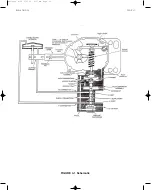
Страница 21: ...BULLETIN F 56 PAGE 21 FIGURE 4 1 Schematic Bulletin F 56 6 27 05 9 37 AM Page 21...


