


3
Notes:
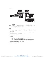
1. The instrument may be powered from the AC line or 24 VDC. Do not wire AC line terminals 1-2 on
the lower board and 24 VDC terminals 4-5 on the upper board at the same time or damage to the
unit will result.
2. For supply connections, wire in accordance with an equivalent national standard or code. Use
copper conductors only rated for at least 75°C.
3. Terminals on upper board are rated CLASS 2.
4.
ISOLATION:
Relays - 1500 VAC to all other inputs and outputs.
AC Line Power (terminals 4-5) - 1500 VAC to all other inputs and outputs.
RS485 output - 500 VAC to all other CLASS 2 wiring.
The 24 VDC Power, 4-20 mA transmitter, and Remote Reset Switch share a common
ground.
5. The Remote Reset Switch must be a dry contact switch.
6. Shielded cable is required for RS485 wiring.
WIRING
WARNING
If Digihelic
®
II Controller is powered by 24 VDC, the device receiving the 4-20 mA
transmitter output MUST NOT share a common ground with the 24 VDC supply or
damage to the Digihelic
®
II Controller will result.
m
1
1
2
1
2
3
1
2
3
4
1
2
3
4
5
1
2
3
4
5
6
1
2
3
4
5
6
7
1
2
3
4
5
6
7
8
1
2
3
4
5
6
7
8
1
1 2
1 2 3
1 2 3 4
1 2 3 4 5
1 2 3 4 5 6
1 2 3 4 5 6 7
1 2 3 4 5 6 7 8
1 2 3 4 5 6 7 8
CONNECTOR
1 2 3 4 5 6 7 8
C
1 2 3 4 5 6 7 8
CO
1 2 3 4 5 6 7 8
CON
1 2 3 4 5 6 7 8
CONN
1 2 3 4 5 6 7 8
CONNE
1 2 3 4 5 6 7 8
CONNEC
1 2 3 4 5 6 7 8
CONNECT
1 2 3 4 5 6 7 8
CONNECTO
1 2 3 4 5 6 7 8
CONNECTOR
ON
1 2 3 4 5 6 7 8
CONNECTOR
O
1 2 3 4 5 6 7 8
CONNECTOR
ON
LOWER
1 2 3 4 5 6 7 8
CONNECTOR
ON
L
1 2 3 4 5 6 7 8
CONNECTOR
ON
LO
1 2 3 4 5 6 7 8
CONNECTOR
ON
LOW
1 2 3 4 5 6 7 8
CONNECTOR
ON
LOWE
1 2 3 4 5 6 7 8
CONNECTOR
ON
LOWER
BOARD
1 2 3 4 5 6 7 8
CONNECTOR
ON
LOWER
B
1 2 3 4 5 6 7 8
CONNECTOR
ON
LOWER
BO
1 2 3 4 5 6 7 8
CONNECTOR
ON
LOWER
BOA
1 2 3 4 5 6 7 8
CONNECTOR
ON
LOWER
BOAR
1 2 3 4 5 6 7 8
CONNECTOR
ON
LOWER
BOARD
CONNECTOR
1 2 3 4 5 6 7 8
CONNECTOR
ON
LOWER
BOARD
C
1 2 3 4 5 6 7 8
CONNECTOR
ON
LOWER
BOARD
CO
1 2 3 4 5 6 7 8
CONNECTOR
ON
LOWER
BOARD
CON
1 2 3 4 5 6 7 8
CONNECTOR
ON
LOWER
BOARD
CONN
1 2 3 4 5 6 7 8
CONNECTOR
ON
LOWER
BOARD
CONNE
1 2 3 4 5 6 7 8
CONNECTOR
ON
LOWER
BOARD
CONNEC
1 2 3 4 5 6 7 8
CONNECTOR
ON
LOWER
BOARD
CONNECT
1 2 3 4 5 6 7 8
CONNECTOR
ON
LOWER
BOARD
CONNECTO
1 2 3 4 5 6 7 8
CONNECTOR
ON
LOWER
BOARD
CONNECTOR
ON
1 2 3 4 5 6 7 8
CONNECTOR
ON
LOWER
BOARD
CONNECTOR
O
1 2 3 4 5 6 7 8
CONNECTOR
ON
LOWER
BOARD
CONNECTOR
ON
UPPER
1 2 3 4 5 6 7 8
CONNECTOR
ON
LOWER
BOARD
CONNECTOR
ON
U
1 2 3 4 5 6 7 8
CONNECTOR
ON
LOWER
BOARD
CONNECTOR
ON
UP
1 2 3 4 5 6 7 8
CONNECTOR
ON
LOWER
BOARD
CONNECTOR
ON
UPP
1 2 3 4 5 6 7 8
CONNECTOR
ON
LOWER
BOARD
CONNECTOR
ON
UPPE
1 2 3 4 5 6 7 8
CONNECTOR
ON
LOWER
BOARD
CONNECTOR
ON
UPPER
BOARD
1 2 3 4 5 6 7 8
CONNECTOR
ON
LOWER
BOARD
CONNECTOR
ON
UPPER
B
1 2 3 4 5 6 7 8
CONNECTOR
ON
LOWER
BOARD
CONNECTOR
ON
UPPER
BO
1 2 3 4 5 6 7 8
CONNECTOR
ON
LOWER
BOARD
CONNECTOR
ON
UPPER
BOA
1 2 3 4 5 6 7 8
CONNECTOR
ON
LOWER
BOARD
CONNECTOR
ON
UPPER
BOAR
1 2 3 4 5 6 7 8
CONNECTOR
ON
LOWER
BOARD
CONNECTOR
ON
UPPER
BOARD
100-240
1
10
100
100-
100-2
100-24
100-240 VAC
100-240 V
100-240 VA
100-240 VAC or
100-240 VAC o
100-240 VAC or
132-240
100-240 VAC o r
1
100-240 VAC or
13
100-240 VAC o r
132
100-240 VAC o r
132-
100-240 VAC o r
132-2
100-240 VAC o r
132-24
100-240 VAC o r
132-240 VDC
100-240 VAC o r
132-240 V
100-240 VAC o r
132-240 VD
100-240 VAC o r
132-240 VDC POWER
100-240 VAC o r
132-240 VDC P
100-240 VAC o r
132-240 VDC PO
100-240 VAC o r
132-240 VDC POW
100-240 VAC o r
132-240 VDC POWE
100-240 VAC o r
132-240 VDC POWER
NOTE
100-240 VAC o r
132-240 VDC POWER
N
100-240 VAC o r
132-240 VDC POWER
NO
100-240 VAC o r
132-240 VDC POWER
NOT
100-240 VAC o r
132-240 VDC POWER
NOTE 1
100-240 VAC o r
132-240 VDC POWER
NOTE 1
3/8
100-240 VAC o r
132-240 VDC POWER
NOTE 1
3
100-240 VAC o r
132-240 VDC POWER
NOTE 1
3/
100-240 VAC o r
132-240 VDC POWER
NOTE 1
3/8 A
100-240 VAC o r
132-240 VDC POWER
NOTE 1
3/8 A 250vac
100-240 VAC o r
132-240 VDC POWER
NOTE 1
3/8 A 2
100-240 VAC o r
132-240 VDC POWER
NOTE 1
3/8 A 25
100-240 VAC o r
132-240 VDC POWER
NOTE 1
3/8 A 250
100-240 VAC o r
132-240 VDC POWER
NOTE 1
3/8 A 250v
100-240 VAC o r
132-240 VDC POWER
NOTE 1
3/8 A 250va
100-240 VAC o r
132-240 VDC POWER
NOTE 1
3/8 A 250vac
MEDIUM
100-240 VAC o r
132-240 VDC POWER
NOTE 1
3/8 A 250vac
M
100-240 VAC o r
132-240 VDC POWER
NOTE 1
3/8 A 250vac
ME
100-240 VAC o r
132-240 VDC POWER
NOTE 1
3/8 A 250vac
MED
100-240 VAC o r
132-240 VDC POWER
NOTE 1
3/8 A 250vac
MEDI
100-240 VAC o r
132-240 VDC POWER
NOTE 1
3/8 A 250vac
MEDIU
100-240 VAC o r
132-240 VDC POWER
NOTE 1
3/8 A 250vac
MEDIUM LAG
100-240 VAC o r
132-240 VDC POWER
NOTE 1
3/8 A 250vac
MEDIUM L
100-240 VAC o r
132-240 VDC POWER
NOTE 1
3/8 A 250vac
MEDIUM LA
100-240 VAC o r
132-240 VDC POWER
NOTE 1
3/8 A 250vac
MEDIUM LAG
N/C
100-240 VAC o r
132-240 VDC POWER
NOTE 1
3/8 A 250vac
MEDIUM LAG
N
100-240 VAC o r
132-240 VDC POWER
NOTE 1
3/8 A 250vac
MEDIUM LAG
N/
100-240 VAC o r
132-240 VDC POWER
NOTE 1
3/8 A 250vac
MEDIUM LAG
N/C
N/C
N
N/
N/C
N/O
N
N/
N/O
N/O
N
N/
N/O
C
C
C
C
SP1
S
SP
SP1
RELAY
SP1
R
SP1
RE
SP1
REL
SP1
RELA
SP1
RELAY
SP2
SP1
RELAY
S
SP1
RELAY
SP
SP1
RELAY
SP2 OR
SP1
RELAY
SP2 O
SP1
RELAY
SP2 OR
ALARM
SP1
RELAY
SP2 OR
A
SP1
RELAY
SP2 OR
AL
SP1
RELAY
SP2 OR
ALA
SP1
RELAY
SP2 OR
ALAR
SP1
RELAY
SP2 OR
ALARM
RELAY
SP1
RELAY
SP2 OR
ALARM
R
SP1
RELAY
SP2 OR
ALARM
RE
SP1
RELAY
SP2 OR
ALARM
REL
SP1
RELAY
SP2 OR
ALARM
RELA
SP1
RELAY
SP2 OR
ALARM
RELAY
A-
SP1
RELAY
SP2 OR
ALARM
RELAY
A
SP1
RELAY
SP2 OR
ALARM
RELAY
A-
B+
SP1
RELAY
SP2 OR
ALARM
RELAY
A-
B
SP1
RELAY
SP2 OR
ALARM
RELAY
A-
B+
RS485
SP1
RELAY
SP2 OR
ALARM
RELAY
A-
B+
R
SP1
RELAY
SP2 OR
ALARM
RELAY
A-
B+
RS
SP1
RELAY
SP2 OR
ALARM
RELAY
A-
B+
RS4
SP1
RELAY
SP2 OR
ALARM
RELAY
A-
B+
RS48
SP1
RELAY
SP2 OR
ALARM
RELAY
A-
B+
RS485 SERIAL
SP1
RELAY
SP2 OR
ALARM
RELAY
A-
B+
RS485 S
SP1
RELAY
SP2 OR
ALARM
RELAY
A-
B+
RS485 SE
SP1
RELAY
SP2 OR
ALARM
RELAY
A-
B+
RS485 SER
SP1
RELAY
SP2 OR
ALARM
RELAY
A-
B+
RS485 SERI
SP1
RELAY
SP2 OR
ALARM
RELAY
A-
B+
RS485 SERIA
SP1
RELAY
SP2 OR
ALARM
RELAY
A-
B+
RS485 SERIAL
COMMUNICATION
SP1
RELAY
SP2 OR
ALARM
RELAY
A-
B+
RS485 SERIA L
C
SP1
RELAY
SP2 OR
ALARM
RELAY
A-
B+
RS485 SERIA L
CO
SP1
RELAY
SP2 OR
ALARM
RELAY
A-
B+
RS485 SERIA L
COM
SP1
RELAY
SP2 OR
ALARM
RELAY
A-
B+
RS485 SERIA L
COMM
SP1
RELAY
SP2 OR
ALARM
RELAY
A-
B+
RS485 SERIA L
COMMU
SP1
RELAY
SP2 OR
ALARM
RELAY
A-
B+
RS485 SERIA L
COMMUN
SP1
RELAY
SP2 OR
ALARM
RELAY
A-
B+
RS485 SERIA L
COMMUNI
SP1
RELAY
SP2 OR
ALARM
RELAY
A-
B+
RS485 SERIA L
COMMUNIC
SP1
RELAY
SP2 OR
ALARM
RELAY
A-
B+
RS485 SERIA L
COMMUNICA
SP1
RELAY
SP2 OR
ALARM
RELAY
A-
B+
RS485 SERIA L
COMMUNICAT
SP1
RELAY
SP2 OR
ALARM
RELAY
A-
B+
RS485 SERIA L
COMMUNICATI
SP1
RELAY
SP2 OR
ALARM
RELAY
A-
B+
RS485 SERIA L
COMMUNICATIO
SP1
RELAY
SP2 OR
ALARM
RELAY
A-
B+
RS485 SERIA L
COMMUNICATION
+
+
-
+
-
24
+
-
2
+
-
24 VDC
+
-
24 V
+
-
24 VD
+
-
24 VDC POWER
+
-
24 VDC P
+
-
24 VDC PO
+
-
24 VDC POW
+
-
24 VDC POWE
+
-
24 VDC POWER
NOTE
+
-
24 VDC POWER
N
+
-
24 VDC POWER
NO
+
-
24 VDC POWER
NOT
+
-
24 VDC POWER
NOTE 1
+
-
24 VDC POWER
NOTE 1
REMOTE
R
RE
REM
REMO
REMOT
REMOTE
RESET
REMOTE
R
REMOTE
RE
REMOTE
RES
REMOTE
RESE
REMOTE
RESET
SWITCH
REMOTE
RESET
S
REMOTE
RESET
SW
REMOTE
RESET
SWI
REMOTE
RESET
SWIT
REMOTE
RESET
SWITC
REMOTE
RESET
SWITCH
Device
REMOTE
RESET
SWITCH
D
REMOTE
RESET
SWITCH
De
REMOTE
RESET
SWITCH
Dev
REMOTE
RESET
SWITCH
Devi
REMOTE
RESET
SWITCH
Devic
REMOTE
RESET
SWITCH
Device receiving
REMOTE
RESET
SWITCH
Device r
REMOTE
RESET
SWITCH
Device re
REMOTE
RESET
SWITCH
Device rec
REMOTE
RESET
SWITCH
Device rece
REMOTE
RESET
SWITCH
Device recei
REMOTE
RESET
SWITCH
Device receiv
REMOTE
RESET
SWITCH
Device receivi
REMOTE
RESET
SWITCH
Device receivin
REMOTE
RESET
SWITCH
Device receiving 4-20mA
REMOTE
RESET
SWITCH
Device receiving 4
REMOTE
RESET
SWITCH
Device receiving 4-
REMOTE
RESET
SWITCH
Device receiving 4-2
REMOTE
RESET
SWITCH
Device receiving 4-20
REMOTE
RESET
SWITCH
Device receiving 4-20m
REMOTE
RESET
SWITCH
Device receiving 4-20mA
signal.
REMOTE
RESET
SWITCH
Device receiving 4-20mA
s
REMOTE
RESET
SWITCH
Device receiving 4-20mA
si
REMOTE
RESET
SWITCH
Device receiving 4-20mA
sig
REMOTE
RESET
SWITCH
Device receiving 4-20mA
sign
REMOTE
RESET
SWITCH
Device receiving 4-20mA
signa
REMOTE
RESET
SWITCH
Device receiving 4-20mA
signal
REMOTE
RESET
SWITCH
Device receiving 4-20mA
signal. Check
REMOTE
RESET
SWITCH
Device receiving 4-20mA
signal. C
REMOTE
RESET
SWITCH
Device receiving 4-20mA
signal. Ch
REMOTE
RESET
SWITCH
Device receiving 4-20mA
signal. Che
REMOTE
RESET
SWITCH
Device receiving 4-20mA
signal. Chec
REMOTE
RESET
SWITCH
Device receiving 4-20mA
signal. Check specifications
REMOTE
RESET
SWITCH
Device receiving 4-20mA
signal. Check s
REMOTE
RESET
SWITCH
Device receiving 4-20mA
signal. Check sp
REMOTE
RESET
SWITCH
Device receiving 4-20mA
signal. Check spe
REMOTE
RESET
SWITCH
Device receiving 4-20mA
signal. Check spec
REMOTE
RESET
SWITCH
Device receiving 4-20mA
signal. Check speci
REMOTE
RESET
SWITCH
Device receiving 4-20mA
signal. Check specifi
REMOTE
RESET
SWITCH
Device receiving 4-20mA
signal. Check specific
REMOTE
RESET
SWITCH
Device receiving 4-20mA
signal. Check specifica
REMOTE
RESET
SWITCH
Device receiving 4-20mA
signal. Check specificat
REMOTE
RESET
SWITCH
Device receiving 4-20mA
signal. Check specificati
REMOTE
RESET
SWITCH
Device receiving 4-20mA
signal. Check specificatio
REMOTE
RESET
SWITCH
Device receiving 4-20mA
signal. Check specification
REMOTE
RESET
SWITCH
Device receiving 4-20mA
signal. Check specifications
of
REMOTE
RESET
SWITCH
Device receiving 4-20mA
signal. Check specifications
o
REMOTE
RESET
SWITCH
Device receiving 4-20mA
signal. Check specifications
of this
REMOTE
RESET
SWITCH
Device receiving 4-20mA
signal. Check specifications
of t
REMOTE
RESET
SWITCH
Device receiving 4-20mA
signal. Check specifications
of th
REMOTE
RESET
SWITCH
Device receiving 4-20mA
signal. Check specifications
of thi
REMOTE
RESET
SWITCH
Device receiving 4-20mA
signal. Check specifications
of this device
REMOTE
RESET
SWITCH
Device receiving 4-20mA
signal. Check specifications
of this d
REMOTE
RESET
SWITCH
Device receiving 4-20mA
signal. Check specifications
of this de
REMOTE
RESET
SWITCH
Device receiving 4-20mA
signal. Check specifications
of this dev
REMOTE
RESET
SWITCH
Device receiving 4-20mA
signal. Check specifications
of this devi
REMOTE
RESET
SWITCH
Device receiving 4-20mA
signal. Check specifications
of this devic
REMOTE
RESET
SWITCH
Device receiving 4-20mA
signal. Check specifications
of this device for
REMOTE
RESET
SWITCH
Device receiving 4-20mA
signal. Check specifications
of this device f
REMOTE
RESET
SWITCH
Device receiving 4-20mA
signal. Check specifications
of this device fo
REMOTE
RESET
SWITCH
Device receiving 4-20mA
signal. Check specifications
of this device for input
REMOTE
RESET
SWITCH
Device receiving 4-20mA
signal. Check specifications
of this device for i
REMOTE
RESET
SWITCH
Device receiving 4-20mA
signal. Check specifications
of this device for in
REMOTE
RESET
SWITCH
Device receiving 4-20mA
signal. Check specifications
of this device for inp
REMOTE
RESET
SWITCH
Device receiving 4-20mA
signal. Check specifications
of this device for inpu
REMOTE
RESET
SWITCH
Device receiving 4-20mA
signal. Check specifications
of this device for input load
REMOTE
RESET
SWITCH
Device receiving 4-20mA
signal. Check specifications
of this device for input l
REMOTE
RESET
SWITCH
Device receiving 4-20mA
signal. Check specifications
of this device for input lo
REMOTE
RESET
SWITCH
Device receiving 4-20mA
signal. Check specifications
of this device for input loa
REMOTE
RESET
SWITCH
Device receiving 4-20mA
signal. Check specifications
of this device for input load
resistance.
REMOTE
RESET
SWITCH
Device receiving 4-20mA
signal. Check specifications
of this device for input load
r
REMOTE
RESET
SWITCH
Device receiving 4-20mA
signal. Check specifications
of this device for input load
re
REMOTE
RESET
SWITCH
Device receiving 4-20mA
signal. Check specifications
of this device for input load
res
REMOTE
RESET
SWITCH
Device receiving 4-20mA
signal. Check specifications
of this device for input load
resi
REMOTE
RESET
SWITCH
Device receiving 4-20mA
signal. Check specifications
of this device for input load
resis
REMOTE
RESET
SWITCH
Device receiving 4-20mA
signal. Check specifications
of this device for input load
resist
REMOTE
RESET
SWITCH
Device receiving 4-20mA
signal. Check specifications
of this device for input load
resista
REMOTE
RESET
SWITCH
Device receiving 4-20mA
signal. Check specifications
of this device for input load
resistan
REMOTE
RESET
SWITCH
Device receiving 4-20mA
signal. Check specifications
of this device for input load
resistanc
REMOTE
RESET
SWITCH
Device receiving 4-20mA
signal. Check specifications
of this device for input load
resistance
REMOTE
RESET
SWITCH
Device receiving 4-20mA
signal. Check specifications
of this device for input load
resistance. Typical
REMOTE
RESET
SWITCH
Device receiving 4-20mA
signal. Check specifications
of this device for input load
resistance. T
REMOTE
RESET
SWITCH
Device receiving 4-20mA
signal. Check specifications
of this device for input load
resistance. Ty
REMOTE
RESET
SWITCH
Device receiving 4-20mA
signal. Check specifications
of this device for input load
resistance. Typ
REMOTE
RESET
SWITCH
Device receiving 4-20mA
signal. Check specifications
of this device for input load
resistance. Typi
REMOTE
RESET
SWITCH
Device receiving 4-20mA
signal. Check specifications
of this device for input load
resistance. Typic
REMOTE
RESET
SWITCH
Device receiving 4-20mA
signal. Check specifications
of this device for input load
resistance. Typica
REMOTE
RESET
SWITCH
Device receiving 4-20mA
signal. Check specifications
of this device for input load
resistance. Typical 250
REMOTE
RESET
SWITCH
Device receiving 4-20mA
signal. Check specifications
of this device for input load
resistance. Typical 2
REMOTE
RESET
SWITCH
Device receiving 4-20mA
signal. Check specifications
of this device for input load
resistance. Typical 25
REMOTE
RESET
SWITCH
Device receiving 4-20mA
signal. Check specifications
of this device for input load
resistance. Typical 250 to
REMOTE
RESET
SWITCH
Device receiving 4-20mA
signal. Check specifications
of this device for input load
resistance. Typical 250 t
REMOTE
RESET
SWITCH
Device receiving 4-20mA
signal. Check specifications
of this device for input load
resistance. Typical 250 to
600
REMOTE
RESET
SWITCH
Device receiving 4-20mA
signal. Check specifications
of this device for input load
resistance. Typical 250 to
6
REMOTE
RESET
SWITCH
Device receiving 4-20mA
signal. Check specifications
of this device for input load
resistance. Typical 250 to
60
REMOTE
RESET
SWITCH
Device receiving 4-20mA
signal. Check specifications
of this device for input load
resistance. Typical 250 to
600 OHMS,
REMOTE
RESET
SWITCH
Device receiving 4-20mA
signal. Check specifications
of this device for input load
resistance. Typical 250 to
600 O
REMOTE
RESET
SWITCH
Device receiving 4-20mA
signal. Check specifications
of this device for input load
resistance. Typical 250 to
600 OH
REMOTE
RESET
SWITCH
Device receiving 4-20mA
signal. Check specifications
of this device for input load
resistance. Typical 250 to
600 OHM
REMOTE
RESET
SWITCH
Device receiving 4-20mA
signal. Check specifications
of this device for input load
resistance. Typical 250 to
600 OHMS
REMOTE
RESET
SWITCH
Device receiving 4-20mA
signal. Check specifications
of this device for input load
resistance. Typical 250 to
600 OHMS, 900
REMOTE
RESET
SWITCH
Device receiving 4-20mA
signal. Check specifications
of this device for input load
resistance. Typical 250 to
600 OHMS, 9
REMOTE
RESET
SWITCH
Device receiving 4-20mA
signal. Check specifications
of this device for input load
resistance. Typical 250 to
600 OHMS, 90
REMOTE
RESET
SWITCH
Device receiving 4-20mA
signal. Check specifications
of this device for input load
resistance. Typical 250 to
600 OHMS, 900 OHMS
REMOTE
RESET
SWITCH
Device receiving 4-20mA
signal. Check specifications
of this device for input load
resistance. Typical 250 to
600 OHMS, 900 O
REMOTE
RESET
SWITCH
Device receiving 4-20mA
signal. Check specifications
of this device for input load
resistance. Typical 250 to
600 OHMS, 900 OH
REMOTE
RESET
SWITCH
Device receiving 4-20mA
signal. Check specifications
of this device for input load
resistance. Typical 250 to
600 OHMS, 900 OHM
REMOTE
RESET
SWITCH
Device receiving 4-20mA
signal. Check specifications
of this device for input load
resistance. Typical 250 to
600 OHMS, 900 OHMS
maximum.
REMOTE
RESET
SWITCH
Device receiving 4-20mA
signal. Check specifications
of this device for input load
resistance. Typical 250 to
600 OHMS, 900 OHMS
m
REMOTE
RESET
SWITCH
Device receiving 4-20mA
signal. Check specifications
of this device for input load
resistance. Typical 250 to
600 OHMS, 900 OHMS
ma
REMOTE
RESET
SWITCH
Device receiving 4-20mA
signal. Check specifications
of this device for input load
resistance. Typical 250 to
600 OHMS, 900 OHMS
max
REMOTE
RESET
SWITCH
Device receiving 4-20mA
signal. Check specifications
of this device for input load
resistance. Typical 250 to
600 OHMS, 900 OHMS
maxi
REMOTE
RESET
SWITCH
Device receiving 4-20mA
signal. Check specifications
of this device for input load
resistance. Typical 250 to
600 OHMS, 900 OHMS
maxim
REMOTE
RESET
SWITCH
Device receiving 4-20mA
signal. Check specifications
of this device for input load
resistance. Typical 250 to
600 OHMS, 900 OHMS
maximu
REMOTE
RESET
SWITCH
Device receiving 4-20mA
signal. Check specifications
of this device for input load
resistance. Typical 250 to
600 OHMS, 900 OHMS
maximum
REMOTE
RESET
SWITCH
Device receiving 4-20mA
signal. Check specifications
of this device for input load
resistance. Typical 250 to
600 OHMS, 900 OHMS
maximum.
+
+
-
+
-
4-20mA
4
4-
4-2
4-20
4-20m
4-20mA
TRANSMITTER
4-20mA
T
4-20mA
TR
4-20mA
TRA
4-20mA
TRAN
4-20mA
TRANS
4-20mA
TRANSM
4-20mA
TRANSMI
4-20mA
TRANSMIT
4-20mA
TRANSMITT
4-20mA
TRANSMITTE
4-20mA
TRANSMITTER
OUTPUT
4-20mA
TRANSMITTER
O
4-20mA
TRANSMITTER
OU
4-20mA
TRANSMITTER
OUT
4-20mA
TRANSMITTER
OUTP
4-20mA
TRANSMITTER
OUTPU
4-20mA
TRANSMITTER
OUTPUT
www.
GlobalTestSupply
.com
Find Quality Products Online at:


