
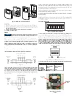


Figure 3 shows how to connect the CDTA in a network containing individual local
supplies. Use a cable containing a twisted pair and a single conductor. The pair is to
be used for B(+) and A(-). The single conductor is to be used for common. Both AC and
DC supplies are suitable for this configuration.
In either configuration you must use shielded cable. Connect the shield to earth ground
at one location only to prevent ground loops.
All devices in the network should be daisy chained. Star connections and T connections
are not permitted.
The B(+) and A(-) lines must be terminated at both ends with a 120 ohm resistor. If the
CDTA is an end device it has an on-board resistor that may be used. See DIP SWITCH
SETTINGS to enable it.
Dip Switch Configuration
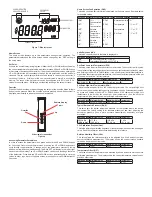
Use DIP Switch SW2 (see Figure 4) to configure the RS-485 MAC address of the
device. A valid address depends on the protocol selected. Valid BACnet addresses
range from 0 to 127. Valid Modbus
®
addresses range from 1 to 247. By default, the
device is shipped with BACnet selected and the address set to 127 (as shown in
Figure 4). A valid and unused address should be set before connecting to an existing
network. The device will not function properly if an invalid address is set. During the
power up sequence, the LCD (if present) will display the RS-485 address as the
primary value with “ADR” as the primary text and either “BAC” to indicate BACnet
or “MOD” to indicate Modbus
®
as the secondary text. If the RS-485 MAC address is
invalid, the invalid value is shown as the primary value with “ERR” as the primary text.
Use DIP Switch SW1 (see Figure 5) to configure other hardware and software options.
MOUNTING
1. Push tab on top and bottom of cover and lift cover from back plate (See Figure 1).
2. Select the mounting location, away from diffusers, lights or any external influences.
3. Mount transmitter on a vertical surface to a standard electrical box using the two #6
M2C type screws provided.
4. Pull wires through sub base hole and make necessary connections.
5. Reattach cover to base plate.
WIRING
Figure 2 shows how to connect the CDTA in a network containing a common power
supply. Use a cable containing two twisted pairs. One pair is to be used for B(+) and A(-
). The other pair is to be used for power and common. This configuration is not suitable
for AC supplies. Use a DC supply only. Care should be taken that there are not too
many devices powered from the same supply as voltage drops will occur in the wiring.
If you have many devices, or have long cable runs, the local supply configuration may
be a better choice.
Figure 1: Removal of cover from back plate
Figure 4: Dip switch SW2 (center-left)
Figure 5: Dip switch SW1 (bottom-center)
Internal view of transmitter
Figure 6
Dip switch
SW2
Dip switch
SW1
Figure 2
Figure 3
Wiring should comply with Electrical Characteristics of Generators
and Receivers for Use in Balanced Digital Multipoint Systems, TIA/
EIA-485-A-1998, Telecommunications Industry Association, 1998.
BACnet installations should comply with ANSI/ASHRAE Standard 135-2010 BACnet
A Data Communication Protocol for Building Automation and Control Networks,
American Society of Heating, Refrigerating and Air-Conditioning Engineers, Inc., 2010.
Modbus
®
installations should comply with Modbus
®
Communication Protocol over
Serial Line Specification and Implementation Guide V1.02, Modbus
®
Organization,
Inc., 2006
Communications wiring must be in a daisy-chain fashion. Star connections are not
permitted.
Cable shield must be connected to earth ground at one location only.
NOTICE
Switch
ON
OFF
1 - Menu Enable
2 - Protocol
3 - Reserved
4 - Terminating
Resister
Access to the setup
menu is enabled.
Modbus
120Ω Between A (-)
and B (+)
Access to the setup
menu is disabled.
BACnet
Open
ON
1 2 3 4 5 6 7 8
PROTOCOL RESERVED
MENU ENABLE
NETWORK TERMINATION
1 2 3 4
ON
COMMON POWER SUPPLY
TO PREVIOUS
DEVICE
TO NEXT
DEVICE
PWR COM B(+) A(-)
PWR
COM
B(+)
A(-)
PWR
COM
B(+)
A(-)
1 2 3 4
LOCAL POWER SUPPLY
TO PREVIOUS
DEVICE
POWER
SUPPLY
TO NEXT
DEVICE
PWR COM B(+) A(-)
COM
B(+)
A(-)
COM
B(+)
A(-)
1 2 3 4


