background image

1036100102L02  1904V002

 7

Product description

4  Technical data

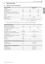
4.1  P2B-304, article 1036100100

Electrical data

1036100100

Voltage

V

400 / 3~

Electrical frequency

Hz

50 

 60

Rated power

kW

4.4 

6.0 

Nominal current at 8 bar (0.8 MPa)

A

8.8 

9.6 

Motor protection switch, recommended 
setting

A

4.4 

5.0 

Speed

min

-1

1440

1700 

Type of protection

IP X4

Mains fusing

A

10 **

Mains connection

CEE 16 A   3L + N + PE, PVC hose connection 5 x 1.5 

mm²;         length: 2.5 m;  

**  Circuit breaker fuse characteristics B, C or D in accordance with DIN EN 60898

General technical data

Pressure vessel volume

 L

90

Delivery at 5 bar (0.5 MPa)

l/min

430 

480 

Pressure build-up phase 0 - 7.5 bar (0 - 
0.75 MPa) approx.

s

90

 80 

Duty cycle

%

100

Initial pressure/Cut off pressure

bar (MPa)

6.5 /  8.5 (0.65 / 0.85)

Safety valve, maximum permissible oper-
ating pressure

bar (MPa)

10 (1)

Pressure dew point (at 7 bar / 0.7 MPa)

°C

 +5

Dimensions (W x H x D)

cm

102 x 76 x 62

Weight

kg

143

Noise level

dB(A)

74

 77

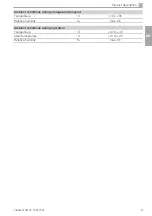
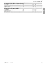
Ambient conditions during storage and transport

Temperature

°C

-10 to +55

Relative humidity

%

max. 95

Ambient conditions during operation

temperature

°C

+5 to +40

Ideal temperature

°C

+10 to +25

Relative humidity

%

Max. 95

EN

Содержание H2A-160M

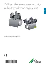
Страница 1: ...Oil free Marathon stations with without membrane drying unit Installation and operating instructions 1036100102L02 1904V002 EN ...

Страница 2: ......
Страница 3: ...ing the filter of the mem brane drying unit 33 12 4 Taking out of use 34 Troubleshooting 13 Tips for operators and service techni cians 35 14 Tips for service technicians 36 EN Contents Important information 1 About this document 3 1 1 Warnings and symbols 3 1 2 Copyright information 3 2 Safety 4 2 1 Intended use 4 2 2 Improper use 4 2 3 General safety information 4 2 4 Specialist personnel 4 2 5 ...

Страница 4: ...2 1036100102L02 1904V002 Contents Contact 15 Addresses 37 15 1 Returns Repairs 37 15 2 To order spare parts 37 15 3 Service 37 15 4 Addresses worldwide 37 EN ...

Страница 5: ... About this document These installation and operating instructions represent a part of the unit They correspond to the relevant version of the unit and the status of technology valid at the time of its market launch In the event that the instructions and notes in these installation and operating instructions for are not observed Dürr Technik accepts no warranty or liability of any kind for the saf...

Страница 6: ...e of incor rect packaging even where the unit is still under guarantee Only transport the unit in its original packag ing Keep the packing materials out of the reach of children 2 Safety Dürr Technik has developed and constructed the units in such a way that danger is to a large extent excluded if the units are used as intend ed Nevertheless residual risks can remain You should therefore observe t...

Страница 7: ...t the unit using the transport handles provided i i Do not transport the unit by the air in take filter The unit may be stored in its original packaging in warm dry and dust free rooms protected from contaminants If possible retain the packaging material 2 8 Disposal Unit Dispose of the unit properly and in ac cordance with applicable national re gional and local laws Packaging Dispose of the pack...

Страница 8: ...tructions Collector tray 3 2 Optional accessories The following optional items can be used with the device Pressure reducer 1013100027 3 3 Wear parts and replacement parts The following working parts need to be changed at regular intervals refer to the Maintenance section Product name Article number Air intake filter cartridge long 0714200050 Fine filter cartridge 0 01 µm 9000 416 0035ET Fine filt...

Страница 9: ...tics B C or D in accordance with DIN EN 60898 General technical data Pressure vessel volume L 90 Delivery at 5 bar 0 5 MPa l min 430 480 Pressure build up phase 0 7 5 bar 0 0 75 MPa approx s 90 80 Duty cycle 100 Initial pressure Cut off pressure bar MPa 6 5 8 5 0 65 0 85 Safety valve maximum permissible oper ating pressure bar MPa 10 1 Pressure dew point at 7 bar 0 7 MPa C 5 Dimensions W x H x D c...

Страница 10: ...0 75 MPa c s 105 95 Duty cycle 100 Start up pressure bar MPa 6 0 6 Cut off pressure bar MPa 7 8 0 78 Cut off pressure max adjustable bar MPa 9 5 0 95 Safety valve maximum permissible oper ating pressure bar MPa 10 1 Pressure dew point at 7 bar 0 7 MPa C 5 Dimensions H x W x D cm 76 x 74 x 52 Weight kg 82 Noise level without sound insulation with sound insulation dB A dB A 70 54 75 55 Value determi...

Страница 11: ...oduct description Ambient conditions during storage and transport Temperature C 10 to 55 Relative humidity max 95 Ambient conditions during operation Temperature C 10 to 40 Ideal temperature C 10 to 25 Relative humidity max 95 EN ...

Страница 12: ...f pressure max adjustable bar MPa 9 5 0 95 Safety valve maximum permissible oper ating pressure bar MPa 10 1 Pressure dew point at 7 bar 0 7 MPa C 5 Dimensions H x W x T cm 76 x 79 x 52 Weight kg 90 Noise level without sound insulation with sound insulation dB A dB A 69 55 74 56 Value determined at an ambient temperature of 40 C With ORANGE rinsing nozzle Values without accessories and add on part...

Страница 13: ...oduct description Ambient conditions during storage and transport Temperature C 10 to 55 Relative humidity max 95 Ambient conditions during operation Temperature C 10 to 40 Ideal temperature C 10 to 25 Relative humidity max 95 EN ...

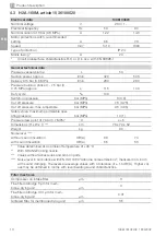
Страница 14: ...uild up phase 0 7 5 bar 0 0 75 MPa approx s 90 80 Duty cycle 100 Switch on pressure bar MPa 6 5 0 65 Cut off pressure bar MPa 8 5 0 85 Cut off pressure max adjustable bar MPa 9 5 0 95 Safety valve maximum permissible oper ating pressure bar MPa 10 1 Pressure dew point at 7 bar 0 7 MPa C 5 Dimensions H x W x T cm 76 x 102 x 62 Weight kg 143 Noise level dB A 69 74 Value determined at an ambient temp...

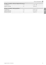
Страница 15: ...oduct description Ambient conditions during storage and transport Temperature C 10 to 55 Relative humidity max 95 Ambient conditions during operation Temperature C 10 to 40 Ideal temperature C 10 to 25 Relative humidity max 95 EN ...

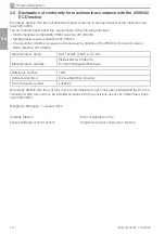
Страница 16: ...ed by directive 2014 68 EC in its current version RoHS directive 2011 65 EU Manufacturer s name Dürr Technik GmbH Co KG Manufacturer s address Pleidelsheimer Straße 30 D 74321 Bietigheim Bissingen Reference number 1036 Article designation Oil free Marathon stations From the serial number L400000 We hereby declare that the unit may only be commissioned once it has been established that the ma chine...

Страница 17: ...t The type plate of the compressor unit is located on the crankcase below the cylinder 1 1 Compressor unit type plate 4 6 Type plate Unit without membrane drying unit Complete system The type plate for the complete system is locat ed on the pressure vessel of the unit 1 1 Type plate for the complete system Compressor unit The type plate of the compressor unit is located on the crankcase below the ...

Страница 18: ... 8 Pressure gauge display 9 Pressure relief valve The compressor unit draws in atmospheric air and compresses it without oil The oil free com pressed air is then transported directly to the pressure tank The oil free and hygienic air is made available to the consumers in the pressure tank Membrane drying unit The type plate of the membrane drying unit is located on the side of the membrane drying ...

Страница 19: ...ng fan 11 Membrane drying unit 12 Pressure limiting valve 13 Humidity display 14 Fine or sterile filter 15 Rinsing nozzle 16 Membrane fibre 17 Sinter filter 18 Water collection chamber 19 Water outlet valve The compressor unit draws in atmospheric air and compresses it without oil It then transports the oil free compressed air to the membrane drying unit The cooler and the membrane dryer extract m...

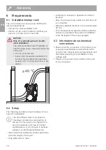
Страница 20: ... for set up must fulfil the fol lowing requirements Closed dry well ventilated room Should not be a room made for another pur pose e g boiler room or wet cell NOTICE Risk of overheating due to insuffi cient ventilation The units generates heat Possibility of heat damage and or reduced service life of the unit i i Do not cover the unit i i Install a fan for auxiliary ventilation in rooms where ambi...

Страница 21: ... pressure hose and the pressure switch A pressure reducer can also be con nected i i The compressed air supply is connected to the quick release coupling incl hose adapter piece or to the pressure switch by means of a G 1 4 internal thread i i Secure the pressure hose to the hose adapter piece using a hose clip i i Connect the hose adapter piece to the quick release coupling 7 Transport WARNING Ri...

Страница 22: ...lling the unit with the membrane drying unit For weight reasons the unit is not supplied fully assembled Instead the compressor units are installed at the site of use i i Set up the tank at the planned installation site i i Screw in the vibration dampers into the motor mounting i i Place the compressors on the vibration damp ers i i Attach the compressor units with the lock washers and nuts i i In...

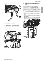
Страница 23: ...st be let off in regular inter vals i i Place a collector tray under the condensate drain i i Open the condensate drain valve at maximum tank pressure i i Close the condensate drain valve as soon as all of the condensate has been blown out connector Close the lock on the connector housing 3 4 3 Lock 4 Pin connector housing 8 4 Pressure reducer optional i i Insert the pressure reducer into the quic...

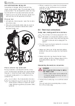
Страница 24: ...t with any hot sur faces on the unit i i Connect the mains plug to an earthed socket outlet The unit will start immediately after connec tion of the mains plug Unit with membrane drying unit Temperature changes during transport may cause condensation water to accumulate in the pressure tank The condensation water can only be drained from the pressurised pressure tank i i Switch on the unit at the ...

Страница 25: ...he values preset at the factory adjust the pressure switch to the factory settings 1 2 1 On off switch 2 Pressure gauge 9 Commissioning 9 1 Check the motor protection switch After installation of the compressor the motor protection switch needs to be checked and ad justed if it is not set up correctly It was set to the recommended setting in the factory see 4 Technical data i i Switch on the unit ...

Страница 26: ...ssure of the station 9 3 Checking the safety valve Check for the correct operation of the safety valve upon commissioning the device and then at regular intervals The safety valve is factory set to 10 bar 1 hPa and has been checked and stamped DANGER Risk of explosion of the pressure vessel and pressure hoses i i Do not change the safety valve set tings i i Switch on the unit at the pressure switc...

Страница 27: ... device i i Use insulated tools i i Do not touch live parts The cut off pressure must be at least 0 5 bar 0 05 hPa below the maximum pres sure of 10 bar 1 hPa of the safety valve Otherwise the safety valve can open too early which will prevent the compressor unit from attaining the cut off pressure as a result of which it will run continuous ly The maximum permitted pressure is marked by a red lin...

Страница 28: ...the cover from the controller i i Adjust the motor protection switch with the adjustment screw to the measured value ob serve the range between the MIN permissible setting and the MAX permissible setting of the motor protection switch see 4 Technical data EN ...

Страница 29: ... 1 A1 X1 X4 4 4 4 5 5 5 PE PE 2 2 1 1 A1 A2 K1 I I I I I I X5 Mains connection 3 N PE AC 230 V Q1 Pressure switch A1 Control box X1 Distributor rail X2 Compressor plug connection X3 Compressor plug connection X4 Distributor rail Q2 Motor protection switch Q3 Motor protection switch K1 Time lag relay M1 Compressor unit M2 Compressor unit M3 Fan motor membrane drying unit optional M4 Fan motor membr...

Страница 30: ...ly 10 2 Unit 1036100600 X1 M1 M2 M3 Q1 1 3 5 2 4 6 1 1 P PE L1L2L3 PE N 3 I I I N X1 Mains connection 3 N PE AC 400 V Q1 Pressure switch M1 Compressor unit M2 Fan motor membrane drying unit M3 Fan motor noise insulation if required EN ...

Страница 31: ...1 A1 3 3 3 2 2 2 1 1 1 7 7 7 PE PE PE PE 2 2 1 1 X1 X4 I I I I I I X5 Mains connection L N PE AC 230 V Q1 Pressure switch A1 Controller X1 Distributor rail X2 Plug connection of compressor unit X3 Plug connection of compressor unit X4 Distributor rail Q1 2 Motor protection switch Q1 3 Motor protection switch M1 Compressor unit M2 Compressor unit M5 Fan motor membrane drying unit EN ...

Страница 32: ... 4 5 5 5 PE PE 2 2 1 1 A1 A2 K1 X5 X4 I I I I I I X1 Mains connection 3 N PE AC 230 V Q1 Pressure switch A1 Control box X2 Plug connection of compressor unit X3 Plug connection of compressor unit X4 Distributor rail X5 Distributor rail Q2 Motor protection switch Q3 Motor protection switch K1 Time lag relay M1 Compressor unit M2 Compressor unit M3 Fan motor membrane drying unit M4 Fan motor membran...

Страница 33: ...1 1 Switching the unit on off i i Switch on the device at the pressure switch by rotating it to the I AUTO position The compressor unit will start up automati cally and fill the pressure vessel When the cut off pressure is reached the compressor unit switches itself off automatically i i The device can be switched off as required by turning the pressure switch to the 0 OFF po sition Usage EN ...

Страница 34: ...he safety valve i i Carry out repeat safety tests e g pressure vessel test electrical safety test in accordance with the national directives Unit with membrane drying unit NOTICE Risk of damage to the unit due to blocked filters Continuous running due to reduced delivery Damage to the unit due to burst filters i i Replace filters in accordance with the maintenance schedule Maintenance interval Mai...

Страница 35: ...the filter cover i i Remove the fine filter 3 mm Fine filter 0 01 mm i i Fit a new 3 mm fine filter 0 01 mm fine filter i i Replace the filter cover and close 12 2 Replacing the air intake filter i i Switch off the compressor at the pressure switch i i Pull off the noise reducer from the air intake fil ter i i Remove the air intake filter i i Insert a new air intake filter i i Push on the noise re...

Страница 36: ...d to the quick release coupling or via the condensate drain valve if present i i Disconnect the compressed air connection on the quick release coupling Storage of the unit WARNING Risk of explosion of the pressure tank and pressure hoses i i The pressure tank and the pressure hoses must be vented before they are stored or transported i i Protect the unit against moisture dirt and ex treme temperat...

Страница 37: ... The compressor is too small air intake too high i i Calculate the amount of air required and install a larger compressor if necessary Leakage in the compressed air system i i Locate and seal the leakage i i Inform a service technician Compressor switches on from time to time even though no air is being tak en for a consumer unit Leak in the compressed air sys tem i i Locate and seal the leak i i ...

Страница 38: ...neces sary switch the circuit breaker back on If the fuse is defective replace it Check the mains supply voltage Undervoltage or overvoltage i i Measure the supply voltage call an electrician if necessary Relief valve defective unit starts against pressure i i Check that the relief valve discharges after switching off the unit Free up the movement of the relief valve operable or replace it Mechani...

Страница 39: ...ng units if possible Always pack the units in a plastic bag Use recyclable packing material 15 2 To order spare parts Tel 49 0 71 42 9022 0 Fax 49 0 71 42 9022 99 E mail office duerr technik de The following information is required when ordering spare parts Type designation and item number Order number as appears on the spare parts list Quantity required Exact shipping address Shipping information...

Страница 40: ...Dürr Technik GmbH Co KG Pleidelsheimer Strasse 30 74321 Bietigheim Bissingen Germany Fon 49 7142 90 22 0 www duerr technik com office duerr technik de ...

Отзывы: