Dürkopp Adler M-TYPE H867 Скачать руководство пользователя страница 28

Setting the stitch length adjusting wheels

26

Service manual H867 Version 00.0 - 08/2013

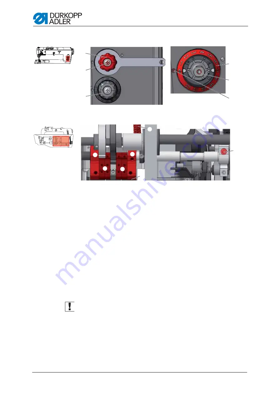
Figure 18: Setting the upper stitch length adjusting wheel - Part 2

6. Check whether the frame (7) for the stitch regulator gear can be moved.

Tip

: In machines that have a stitch adjustment lever, you can check 

this by pressing the stitch adjustment lever.
In machines that do not have a stitch adjustment lever, you can insert 
the locking peg or a hex key into the opening (9) and use it to try and 
move the frame (7) up and down.

7. As soon as the frame (7) no longer moves: 

Remove the wrench from the shaft (5).

8. Turn the scale (6) for the upper stitch length adjusting wheel (1) such 

that the 0 is exactly next to the adjusting mark (4).

9. Place the upper stitch length adjusting wheel (1) onto the shaft (5).

10.Hold the upper stitch length adjusting wheel (1) using a star key.

11.Tighten the upper stitch length adjusting wheel  (1) on the shaft  (5) using 

the screw (2).

12.

Important:

 Check whether the plates for the stitch regulator gear (8) 

are parallel to one another in this position.

If the plates (8) are not parallel to one another:

13.Remove the tension spring (10).

14.Loosen the clamping screw (11).

15.Manually position the plates (8) so that they are parallel.

16.Tighten the clamping screw (11).

17.Attach the tension spring (10).


2

3

5

6

4

1

0

^

7

7

8

8

9

(7) - Frame for the stitch regulator gear
(8) - Plates for the stitch regulator gear
(9) - Opening

(10) - Tension spring
(11) - Clamping screw

(1) - Upper stitch length adjusting wheel
(2) - Screw
(3) - Lower stitch length adjusting wheel

(4) - Adjusting mark
(5) - Shaft
(6) - Scale

Содержание M-TYPE H867

Страница 1: ...H867 Service manual...

Страница 2: ...y of D rkopp Adler AG and protected by copyright Any reuse of these contents including extracts is prohibited without the written approval of D rkopp Adler AG in advance Copyright D rkopp Adler AG 201...

Страница 3: ...4 6 Removing and inserting the throat plate 14 4 4 7 Removing and inserting the feed dog 15 4 5 Surfaces on shafts 16 4 6 Locking the sewing machine in place 16 4 7 Putting the handwheel into position...

Страница 4: ...ead regulator 62 14 2 Setting the thread tensioning spring 63 15 Winder 65 15 1 Position of the winder wheel in long arm machines 65 15 2 Setting the winder 66 15 3 Setting the hook thread guide 69 16...

Страница 5: ...ed in the corresponding manuals of the manufacturers 1 4 Damage during transport D rkopp Adler cannot be held liable for any damage during transport Check the delivered product immediately after recei...

Страница 6: ...anufacturer All warnings on the machine must always be in legible condition and may not be removed Missing or damaged labels must be replaced immedi ately In the following situations the machine must...

Страница 7: ...Only use original spare parts from the manufacturer Missing or faulty spare parts could impair safety and damage the machine 2 2 Layout of safety instructions The safety instruction text is surrounded...

Страница 8: ...iance Measures for avoiding the danger This is what a hazard note looks like for a hazard that could result in serious injury or even death if not complied with WARNING Type and source of the danger C...

Страница 9: ...with the legal requirements concerning environmental protection 3 2 Layout of environmental protection information The environmental protection text is surrounded by green bars The following symbol i...

Страница 10: ...rst setting step 2 Second setting step 3 Third setting step etc The sequence of setting steps must always be followed Result of performing an operation If the machine is changed in one particular sett...

Страница 11: ...aired in their ability to function correctly 1 Lay any excess cabling neatly in proper cable snakes 2 Tie the snakes together using a cable tie If possible bind the snakes to fixed parts The cables mu...

Страница 12: ...of setting work 4 4 1 Access to the machine bottom section In order to access the components at the machine bottom section you must first tilt the machine upper section backwards Figure 1 Tilt the ma...

Страница 13: ...l is positioned at 2 2 Loosen the arm cover screws 1 3 Hold the arm cover 3 at the adjusting wheels and remove it Fitting the arm cover 1 Fit the arm cover 3 2 Screw the arm cover screws 1 firmly in p...

Страница 14: ...and fitting the valve cover Removing the valve cover 1 Loosen all four valve cover screws 1 2 Remove the valve cover 2 Important When removing the valve cover be sure not to pull off any cables Fittin...

Страница 15: ...ng and closing the throat plate slide Opening the throat plate slide 1 Press the clamping spring 3 downwards 2 Push the throat plate slide 1 apart Pushing the throat plate slide back into place 1 Push...

Страница 16: ...he throat plate slide page 13 2 Loosen the throat plate screws 2 3 Remove the throat plate 1 Inserting the throat plate 1 Fit the throat plate 1 2 Screw the throat plate screws 2 firmly in place 3 Pus...

Страница 17: ...f the feed dog carrier 2 Inserting the feed dog 1 Place the feed dog 1 onto the feed dog carrier 2 2 Screw the feed dog screws 3 firmly in place 3 Insert the throat plate Section 4 4 6 Removing and in...

Страница 18: ...tings the machine has to be locked in place To do this the locking peg from the accessory pack is inserted into a groove on the arm shaft crank to block the arm shaft Figure 9 Locking peg and arrestin...

Страница 19: ...locking peg 3 with the appropriate end into the groove 4 Removing the locking mechanism 1 Pull the locking peg 3 out of the groove 4 2 Insert the plug 2 into the locking opening 1 4 7 Putting the han...

Страница 20: ...1 1 Turn the handwheel such that one screw is under the opening 1 2 Loosen the screw using a 3 mm hex key through the opening 1 3 Turn the handwheel such that the second screw is under the opening 1...

Страница 21: ...re 13 Setting the arm shaft crank Setting steps 1 Loosen the three setscrews 3 on the arm shaft crank 1 2 Turn the arm shaft crank 1 such that the setscrews 3 are seated com pletely on the surface of...

Страница 22: ...Differences between the short arm and long arm machines Differences in the setting sequence are caused by the differing position of the winder wheel In long arm machines the winder wheel on the drive...

Страница 23: ...the upper toothed belt wheel must be 0 8 mm Cover Arm cover Section 4 4 2 Removing and fitting the arm cover page 11 Figure 14 Setting the upper toothed belt wheel Setting steps 1 Using the screwdrive...

Страница 24: ...wheel 3 is 0 8 mm 5 Tighten the setscrews 2 6 Use the screwdriver to push the toothed belt 4 back again 7 2 Lower toothed belt wheel Correct setting The two setscrews for the lower toothed belt wheel...

Страница 25: ...ws 4 2 Turn the lower toothed belt wheel 3 such that the setscrews 4 are seated on the surface of the arm shaft 3 Move the lower toothed belt wheel 3 to the side such that the toothed belt 1 makes con...

Страница 26: ...tween the stitch lengths Press the key for the stitch length on the machine arm 1 If the upper adjusting wheel is activated then the key 1 lights up Upon switching on the machine the stitch length adj...

Страница 27: ...per stitch length adjusting wheel Part 1 2 Hold the upper stitch length adjusting wheel 1 using a star key 3 Loosen the screw 2 4 Remove the upper stitch length adjusting wheel 1 from the shaft 5 5 Ca...

Страница 28: ...ly next to the adjusting mark 4 9 Place the upper stitch length adjusting wheel 1 onto the shaft 5 10 Hold the upper stitch length adjusting wheel 1 using a star key 11 Tighten the upper stitch length...

Страница 29: ...adjusting wheel Setting steps 1 Switching over to the smaller stitch lengths The key for the stitch length on the machine arm 1 must be off If it is lit up Press the key 1 2 Repeat steps 2 to 11 from...

Страница 30: ...arge enough that the feed dog does not hit against the edges of the throat plate at the front and rear dead center Correct setting Turn the upper stitch length adjusting wheel to the right as far as i...

Страница 31: ...sting wheel 1 5 Remove the setscrew from one of the three mark off openings 3 6 Screw the setscrew into the mark off opening for the required maximum stitch length The openings are given numbers for t...

Страница 32: ...d and backward stitches Setting steps 1 Loosen the clamp setscrew 2 2 Turn the eccentric screw 3 from the right through the opening in the machine frame Basic position The slot in the eccentric screw...

Страница 33: ...length is 0 the needle pierces exactly in the center of the nee dle hole Various settings have to be made depending on how far the actual posi tion of the feed dog differs from the correct setting For...

Страница 34: ...moving and inserting the throat plate page 14 Figure 22 Moving the feed dog on the feed dog carrier Setting steps 1 Loosen the feed dog screws 3 2 Move the feed dog 1 on the feed dog carrier 2 Place t...

Страница 35: ...rings 2 5 Move the feed dog carrier cross line to the sewing direction such that the feed dog is exactly in the center of the throat plate cut out 6 Push the adjusting rings 2 toward each other as fa...

Страница 36: ...rection 1 Remove the tension spring 8 from the mounting bracket 2 Loosen the connection to the tie rod using the screws 1 3 Loosen the rear assembly frame screw 6 4 Loosen the setscrews for the adjust...

Страница 37: ...ant When doing so make sure that the gear shaft is not moved so far that the plates hit against the sliding shaft 12 Tighten the adjusting ring and fasten the screw 7 13 Tighten the pin and fasten the...

Страница 38: ...ing screw 14 19 Move the feed dog carrier in the sewing direction such that it is exactly in the center of the throat plate cut out 20 Tighten the rear assembly frame screw 6 21 Tighten the connection...

Страница 39: ...t the upper stitch length adjusting wheel to the maximum stitch length If the stitch adjustment lever is pressed downwards then the feed dog will stand still Cover Tilt the upper section backwards Sec...

Страница 40: ...ng Handwheel in the 190 position The upper edge of the feed dog protrudes 0 8 mm above the throat plate Cover Tilt the upper section backwards Section 4 4 1 Access to the machine bottom section page 1...

Страница 41: ...ed dog is in the upward movement at 270 in the downward movement Cover Tilt the upper section backwards Section 4 4 1 Access to the machine bottom section page 10 Figure 30 Setting the feed dog stroke...

Страница 42: ...eight Setting steps 1 Put the handwheel into the 210 position 2 Loosen the setscrew 1 on the compensating weight 2 using a 3 mm hex key 3 Leave the hex key inserted in the setscrew 4 Turn the compensa...

Страница 43: ...Moving the needle bar linkage sideways Cover Arm cover Section 4 4 2 Removing and fitting the arm cover page 11 Head cover Section 4 4 3 Removing and fitting the head cover page 11 Figure 32 Aligning...

Страница 44: ...dle hole 3 for the feed dog 5 Push the two adjusting rings 2 inwards as far as they will go and tighten them 6 Tighten the setscrews 1 on the two adjusting rings 2 7 Align the thread lever 7 exactly i...

Страница 45: ...e screw 1 4 Loosen the setscrews 5 5 Move the needle bar linkage in the sewing direction such that the dis tance between the straight surface 2 of the lever 4 and the outer edge 3 of the rear arm surf...

Страница 46: ...Aligning the needle bar linkage 44 Service manual H867 Version 00 0 08 2013 Sequence Then check the following settings Loop stroke position Section 11 2 Setting the loop stroke position page 47...

Страница 47: ...e clearance Correct setting Machine locked in place in the loop stroke position page 16 Maximum 0 1 mm distance between the hook tip and the groove for the needle Cover Tilt the upper section backward...

Страница 48: ...6 and the groove for the needle 5 is 0 1 mm at most without the hook tip 6 touching the needle 5 Tighten the screws 4 for the hook support 3 Important Check the loop stroke position Section 11 2 Setti...

Страница 49: ...Aligning the needle bar linkage page 41 A straight and undamaged needle has to be inserted Betriebsanleitung Kap 7 3 Nadel einsetzen und wechseln Correct setting Machine locked in place in the loop s...

Страница 50: ...the hook housing 4 Turn the hook such that the hook tip 4 points exactly to the vertical center line of the needle 3 5 Tighten the setscrews 2 for the hook clamping ring 1 6 Remove the locking mechan...

Страница 51: ...e has to be inserted Betriebsanlei tung Kap 7 3 Nadel einsetzen und wechseln Correct setting Machine locked in place in the loop stroke position page 16 The needle guard pushes the needle just enough...

Страница 52: ...andwheel and check how far the needle guard pushes the needle away 2 Turnthescrew 1 ontheneedleguard 2 suchthattheneedleguard 2 just pushes the needle 3 far away enough so that it cannot be touched by...

Страница 53: ...achine locked in place in the loop stroke position page 16 and the upper stitch length adjusting wheel set to 0 The hook tip is at the level of the lower third of the groove for the nee dle Faults cau...

Страница 54: ...ove the height of the needle bar 1 such that the hook tip 4 is in the middle of the lower third of the groove for the needle Important Do not twist the needle to the side in doing so The groove 3 for...

Страница 55: ...appears for the thread If the hook tip is located below the spool housing lifter then the spool housing lifter must open so that the thread can also slide past in that posi tion So that the thread ca...

Страница 56: ...Opening and closing the throat plate slide page 13 Figure 41 Setting the lifting gap Setting steps 1 Loosen the cover screw 3 2 Push the cover 2 downwards 3 Loosen the setscrew 1 4 Set the spool housi...

Страница 57: ...ddle of the opening insert hex key in the setscrew for orientation Cover Tilt the upper section backwards Section 4 4 1 Access to the machine bottom section page 10 Figure 42 Setting the point in time...

Страница 58: ...ght adjusting wheel determines the elevated sewing foot stroke The ele vated sewing foot stroke must not be lower than the normal sewing foot stroke Figure 43 Adjusting wheels for the sewing foot stro...

Страница 59: ...handwheel to the 0 position 2 Loosen the screw 3 for the sewing foot lever 4 3 Lower the presser foot 1 and feeding foot 2 together down to the throat plate Important Make sure that the feeding foot i...

Страница 60: ...ect setting Left adjusting wheel for the sewing foot stroke set to 9 and the upper stitch length adjusting wheel to 0 The feeding foot 1 touches down exactly on the feed dog 2 when the downwards movem...

Страница 61: ...to 0 3 Loosen the stroke eccentric setscrews 2 4 Turn the stroke eccentric 1 such that the feeding foot touches down on the feed dog when the handwheel is in the 95 position Important Do not move the...

Страница 62: ...turning the wheel The correct pressure depends on the material to be sewn Lower pressure for soft materials e g silk Higher pressure for harder materials e g leather Correct setting The material being...

Страница 63: ...ing the sewing foot lifting height Setting steps 1 Loosen the counternut 2 for the adjusting screw 1 2 Turn the adjusting screw 1 to set the distance between the raised sew ing feet and the throat pla...

Страница 64: ...tension for thick material high thread strengths Correct setting The loop of the needle thread slides at low tension over the thickest point of the hook without forming loops or snagging Cover Throat...

Страница 65: ...ng The thread tensioning spring does not contact the stop until the needle eye has plunged into the material being sewn The setting for the thread tensioning spring has to vary according to the materi...

Страница 66: ...n 00 0 08 2013 3 Setting the spring tension Turn the tension disc 3 Greater spring tension Turn the disc to the left Less spring tension Turn the disc to the right Important Do not twist the stop coll...

Страница 67: ...between the winder wheel and the driver wheel is 0 8 mm Cover Arm cover Section 4 4 2 Removing and fitting the arm cover page 11 Figure 51 Setting the distance between the winder wheel and driver whe...

Страница 68: ...ing quantity Setting steps Removing the winder 1 Loosen the winder screws 1 2 Remove the winder Setting the winder filling quantity The position of the arms on the winder flap screw 2 determines the f...

Страница 69: ...will go to the thread Figure 53 Setting the winder run and automatic stop Setting the winder run 6 Loosen the switch cam setscrew 8 7 Set the switch cam 9 such that it is just contacting the leaf spri...

Страница 70: ...bove the marking for the XXXL hook 15 The distance between the winder flap and the outer thread on the bobbin is then 2 3 mm 13 Set the engaging clamp 5 such that it is resting against the locking dis...

Страница 71: ...hook thread guide determines how the thread is wound onto the winder Correct setting The thread is wound on evenly over the entire width of the bobbin Figure 56 Setting the hook thread guide Setting s...

Страница 72: ...e hook and is at the same height as the counter blade 1 Cover Throat plate slide Section 4 4 5 Opening and closing the throat plate slide page 13 Figure 57 Setting the height of the thread pulling kni...

Страница 73: ...knife sideways Part 1 Setting steps 1 Loosen the four setscrews 2 on the hook clamping ring 1 2 Push the hook clamping ring 1 as far as it will go to the left 3 Tighten the four setscrews 2 on the hoo...

Страница 74: ...uating lever 7 such that the actuating lever 7 has no axial play 12 Loosen the four setscrews 2 on the hook clamping ring 1 13 Push the hook clamping ring 1 to the right as far as it will go and again...

Страница 75: ...e thread Cover Throat plate slide Section 4 4 5 Opening and closing the throat plate slide page 13 Figure 60 Setting the cutting pressure Setting steps 1 Turn the handwheel until the thread pulling kn...

Страница 76: ...osing the throat plate slide page 13 Figure 61 Setting the point in time for cutting Setting steps 1 Loosen the control cam setscrews 4 2 Turn the handwheel until the thread pulling knife 6 can be swu...

Страница 77: ...am 3 and the widest extent of the control cam is at hand wheel position 60 at the highest point 7 Tighten the control cam setscrews 4 8 Check Insert the thread into thread pulling knife 6 and slowly t...

Страница 78: ...the main power switch 2 Keep the P key 2 and Reset key 4 pressed down simultaneously and switch on the machine at the main power switch in doing so The display starts 3 Release the P key 2 and Reset...

Страница 79: ...10 Loosen the setscrew 3 for the shaft 11 Turn the potentiometer axle such that the left display shows 1 in the first instance and the relevant maximum speed next to it 12 Tighten the setscrew 3 witho...

Страница 80: ...he coupling has dis engaged they are no longer parallel Cover Tilt the upper section backwards Section 4 4 1 Access to the machine bottom section page 10 Figure 64 Attaching the safety snap on couplin...

Страница 81: ...uch that 8 Nm is reached for the torque To increase the force Turn in the direction To reduce the force Turn in the direction 3 Tighten the coupling screw 3 Risk of crushing Switch off the sewing mach...

Страница 82: ...Avoid any skin contact with the oil If oil gets on your skin wash the affected skin areas thoroughly WARNING Risk of environmental damage from oil Oil is a pollutant and must not enter the sewage sys...

Страница 83: ...l level is below the minimum level marking 3 2 Pour oil through the refill opening 1 but no higher than the maximum level marking 2 CLASSIC equipment Note for machines with CLASSIC equipment If the oi...

Страница 84: ...13 Figure 67 Setting the hook lubrication Setting steps 1 Turn the regulating screw 3 Turning to the left more oil is released Turning to the right less oil is released The released amount of oil does...

Страница 85: ...an 1 bar Figure 68 Setting the operating pressure Setting steps 1 Pull the turning handle 1 up 2 Turn the turning handle until the pressure indicator 2 indicates 6 bar To the right To increase pressur...

Страница 86: ...on Maintenance steps 1 Place the collection tray under the drain screw 3 2 Unscrew the drain screw 3 completely 3 Allow water to drain into the collection tray 4 Tighten the drain screw 3 Machine dama...

Страница 87: ...l 5 Wash out the filter tray using benzine 6 Tighten the filter element 1 7 Tighten the water separator 2 8 Tighten the drain screw 3 Risk of injury Switch off the machine at the main power switch and...

Страница 88: ...o soiling Cutter on the bobbin winder for the hook thread 4 Area under the throat plate 3 Hook 2 Area around the needle 1 Cleaning steps 1 Remove any dust and thread remains using a compressed air pis...

Страница 89: ...move any sewing dust and thread remains using a compressed air pistol Damage to the paintwork due to solvent based cleaners Solvent based cleaners damage the paintwork of the machine Use only solvent...

Страница 90: ...gives no more than 10 mm Cover Tilt the upper section backwards Section 4 4 1 Access to the machine bottom section page 10 Figure 73 Checking the toothed belt Test steps 1 Check the toothed belt for c...

Страница 91: ......

Страница 92: ...er Str 190 33719 Bielefeld Germany Phone 49 0 521 925 00 E Mail service duerkopp adler com www duerkopp adler com Subject to design changes Printed in Germany D rkopp Adler AG Service Instructions 079...

Отзывы: