background image

Programming

Service Instructions 745-35-10 S/745-35-10 A - 02.0 - 04/2017

193

Fig. 168: Copying a seam sequence (3)

• To copy, press 

OK

 to confirm

• To cancel, press the 

Cancel

 button

The display returns to 

Overview of sequences

.

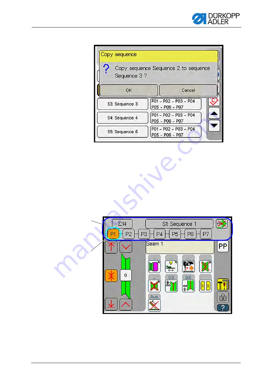
Activating a pocket program from the seam sequence

You can activate a single pocket program stored in the seam sequence 
if you wish to sew a specific pocket program that is not up next in the 
sequence.

Fig. 169: Activating a pocket program from the seam sequence

(1)

- Pocket programs in sequence

(2)

- selected pocket program

Содержание 745-35-10 A

Страница 1: ...745 35 10 S 745 35 10 A Service Instructions...

Страница 2: ...er AG and protected by copyright Any reuse of these contents including extracts is prohibited without the prior written approval of D rkopp Adler AG Copyright D rkopp Adler AG 2017 IMPORTANT READ CARE...

Страница 3: ...needle bar linkage 38 3 8 7 Setting the height of the needle bar linkage 40 3 8 8 Aligning the needle bar linkage with the throat plate 42 3 8 9 Changing the needle holder 43 3 9 Hook 45 3 9 1 Setting...

Страница 4: ...rner knife 745 35 10 A only 101 6 3 2 Checking the rear left corner knife 745 35 10 A only 102 6 4 Aligning the corner knife station with the seams 103 6 5 Setting the slant of the corner knife cuts 1...

Страница 5: ...4 2 Throw over stacker 745 35 10 A only 160 14 2 1 Checking the function sequence 160 14 2 2 Setting the throw over stacker 163 14 2 3 Setting the stacking speed 166 14 2 4 Activating the stacker 166...

Страница 6: ...Table of Contents 4 Service Instructions 745 35 10 S 745 35 10 A 02 0 04 2017 22 4 Pneumatic diagram throw over stacker 378...

Страница 7: ...these instructions intended These instructions are intended for Specialists This group has the appropriate technical training for performing maintenance or repairing malfunctions With regard to minimu...

Страница 8: ...he display control panel Important Special attention must be paid to this point when performing a step Information Additional information e g on alternative operating options Order Specifies the work...

Страница 9: ...ble standards and regulations D rkopp Adler cannot be held liable for any damage resulting from Breakage and damage during transport Failure to observe these instructions Improper use Unauthorized mod...

Страница 10: ...About these instructions 8 Service Instructions 745 35 10 S 745 35 10 A 02 0 04 2017...

Страница 11: ...ulty parts could impair safety and damage the machine Only use original parts from the manufacturer Transport Use a lifting carriage or forklift to transport the machine Raise the machine max 20 mm an...

Страница 12: ...mbols used in warnings Warnings in the text are distinguished by color bars The color scheme is based on the severity of the danger Signal words indicate the severity of the danger Signal words Signal...

Страница 13: ...Safety Service Instructions 745 35 10 S 745 35 10 A 02 0 04 2017 11...

Страница 14: ...s or even fatal injury if ignored This is what a warning looks like for a hazard that could result in moderate or minor injury if the warning is ignored Puncture Crushing Environmental damage Symbol T...

Страница 15: ...ult in envi ronmental damage if ignored This is what a warning looks like for a hazard that could result in property damage if ignored CAUTION Type and source of danger Consequences of non compliance...

Страница 16: ...Safety 14 Service Instructions 745 35 10 S 745 35 10 A 02 0 04 2017...

Страница 17: ...ft crank Fig 1 Slot in the arm shaft crank The arm shaft crank 2 is fitted with a slot 1 5 mm The machine head can be pegged into place in the hole 3 using the lock ing peg When pegged in this positio...

Страница 18: ...he machine head 1 To swivel up the machine head 1 Remove the hood 1 To do so lift the hood 1 up at the front to release the lock Carefully life the hood 1 up and off 2 Pull the handle of the folding s...

Страница 19: ...the machine head 2 5 Raise the fabric sliding plate 4 at the front and swivel it out to the left 6 Lift the machine head in the head cover area 2 and swivel it up carefully The latch 5 locks into plac...

Страница 20: ...ig 5 Swiveling down the machine head 2 To swivel down the machine head 1 Hold the machine head in the head cover area 2 2 Release the latch 5 NOTICE Property damage may occur Needle breakage When swiv...

Страница 21: ...machine head prior to repairs or for a quick and easy switch to a different needle distance This requires that the transport carriage be in its rear position Fig 6 Disassembling the machine head 1 To...

Страница 22: ...head 2 5 Swivel the locking lever 3 up 6 Raise the fabric sliding plate 4 at the front and swivel it out to the left 7 Disconnect the electrical and pneumatic connection to the machine head 8 Loosen t...

Страница 23: ...ble tool to carefully lift the machine head up and out 3 6 Assembling machine head Fig 9 Assembling machine head 1 To assemble the machine head 1 Useasuitabletooltocarefullyinsertthemachineheadintothe...

Страница 24: ...on 5 5 Establish the electrical and pneumatic connection to the machine head 6 Insert the fabric sliding plate 4 7 Swivel the locking lever 3 down Fig 11 Assembling machine head 3 8 Swivel down the fo...

Страница 25: ...andated by the design of the machine The crank pin has been set precisely by the manufacturer It needs to be re adjusted after the thread lever has been replaced or if the needles no longer switch off...

Страница 26: ...24 Service Instructions 745 35 10 S 745 35 10 A 02 0 04 2017 Removing the head cover Fig 12 Removing the head cover To remove the head cover 1 Loosen the screws 1 2 Remove the head cover 2 1 Screws 2...

Страница 27: ...ead tension plate To loosen the thread tension plate 3 Loosen the screws 4 4 Swivel the thread tension plate 5 sideways to the right Disassembling switching cylinder and needle bar linkage Fig 14 Disa...

Страница 28: ...assemble the crank pin 1 Loosen the fastening screws Caution Left handed thread 2 Loosen the needle bar connecting rod from the crank pin 8 and pull it off along with the needle cage 3 Turn the handwh...

Страница 29: ...ad lever 11 must be minimal to allow for oiling 8 Tighten the screw 9 9 Tighten the hexagon screws 14 10 Remove the gage 13 11 Turnthehandwheelandcheckthearmshaftforeaseofmovement 12 12 Slip the needl...

Страница 30: ...head cover To remove the head cover 1 Loosen the screw 1 2 Carefully loosen the clamp for the needle thread monitor 3 The needle thread monitor may become damaged 3 Remove the head cover 2 WARNING Ri...

Страница 31: ...assembling the needle bar linkage Fig 17 Disassembling the needle bar linkage 1 To remove the needle bar linkage 1 Loosen screws 4 and 7 2 Remove the thread advancing device 6 3 Loosen the screw 5 4 L...

Страница 32: ...adjusting screws 9 to set the needle bar linkage frame to the correct height Important Avoid damage to the oil wick when removing the needle bar Take note of the oil wick position for subsequent reas...

Страница 33: ...from the needle bar linkage Fig 19 Removing a needle bar from the needle bar linkage 1 To remove a needle bar from the needle bar linkage 1 Loosen the clamping screw 1 2 Pull out the bearing bolt 3 3...

Страница 34: ...ing down the clamping ring 16 10 Move the switching block to a position where the two decoupling bars 5 are not actuated 11 Slowly slide the crosshead 13 up the needle bar until the three top coupling...

Страница 35: ...ew the screw 1 3 Loosen the needle holder 2 4 Loosen the screw 4 5 Loosen the spring counter bearing 3 Important Spring counter bearing is spring loaded Before loosening screw 4 sup port the spring co...

Страница 36: ...11 and secure the cap nut 12 in such a way that the gap between the lower edge of the taper sleeve 9 and the top edge of the cap nut 12 is 30 5 mm Important Strictly follow this dimension 30 5 mm as...

Страница 37: ...Screw the spring counter bearing 4 firmly in place with the screw 5 8 Repeatedly press down on the decoupling bar 16 to check whether the linkage can move inside the needle bar 3 with enough free move...

Страница 38: ...upper ball holes 6 7 Hold the needle bar 4 in position 8 Press the decoupling bar 13 into the needle bar 4 while pulling the crosshead 9 down at the same time The crosshead is halfway down relative to...

Страница 39: ...ety bolt 14 20 Screw on the guide rail 16 The guide rail 16 prevents a disconnected needle bar from turning Important Do not slide the crosshead 9 down too far when the needle bar linkage is removed a...

Страница 40: ...he support plate 1 but retain its free movement 4 Carefully slide the support plate 1 with the needle bar linkage 2 onto the stop pin 4 5 Insert and slightly tighten the fastening screw 5 6 Move the a...

Страница 41: ...e 2 with the throat plate 9 Tighten the screw 5 10 Check the height of the needle bar linkage p 40 and check the lateral alignment with the needle hole p 42 Fig 27 Assembling the needle bar linkage 3...

Страница 42: ...tance between the crosshead 4 and the needle bar linkage 3 must be 0 2 mm To set the height of the needle bar linkage 1 Loosen the screw 1 2 Remove the head cover 2 3 Verify that the distance between...

Страница 43: ...ly loosen the screw 7 on the support plate 5 Loosen counternuts 8 and 5 6 Use screws 6 and 9 to adjust the height of the linkage The distance between linkage 3 and crosshead 4 is 0 2 mm 7 Tighten coun...

Страница 44: ...ar linkage with the throat plate 1 Insert new needles 2 Slowly turn the handwheel to move the needle bars down 3 Check the position of the needles inside the needle hole 4 Loosen the screws 1 5 Shift...

Страница 45: ...e holder 1 Loosen the screw 3 2 Remove the needle from the needle holder 4 3 Useahexkey 1 topressdownandholdtheswitchrodoftheneedlebar 4 Turn the handwheel to disconnect the needle bar 5 Continue to t...

Страница 46: ...lder 4 from the needle bar 9 Screw in a new needle holder 10 Adjust the height of the needle holder p 50 11 Tighten the screw 3 12 Check how the needle plunges into the needle hole p 42 13 Check the l...

Страница 47: ...surface of the hook shaft 1 must be 17 7 mm The exact height of the hook shaft is set using the gage 3 part number 0244 001001 To adjust the height of the hook shaft 1 Remove the throat plate 2 Remov...

Страница 48: ...7 Loosen the screws found below the plastic stoppers 5 8 Loosen the screws 7 9 Slide the flange surface of the hook shaft 1 under the measuring sleeve 2 of the gage To do so position a screwdriver un...

Страница 49: ...adjustment of the hook drive in axial direction change of the needle distance requires that the gear clearance be readjusted To set the gear clearance of the hook drive 1 Slightly turn the hook while...

Страница 50: ...arance by turning the socket 4 While it should be as low as possible the gear clearance between worm and worm wheel should be noticeable To increase the gear clearance Turn the socket 4 upward To redu...

Страница 51: ...n the handwheel to move the machine head to the loop stroke position and lock the machine head in place using the locking peg 4 Check the position of the hook tips to the needles 5 Swivel up the machi...

Страница 52: ...ng pin 2 part number 0216 001070 To set the needle holder height 1 Remove the throat plate 2 Turn the needle bar to the loop stroke position 3 Insert the locking peg through the hole in the machine ar...

Страница 53: ...turn the handwheel The depressed switch rod switches the needle bar off 10 Relieve the switch rod 11 Insert the measuring pin 2 into the needle holder as far as it will go 12 Tighten the screw 7 13 P...

Страница 54: ...e distance between hook tips and needles 1 Proper setting In the loop stroke position the distance between the hook tips 2 and the needles 1 should be 0 1 mm The set distance makes it possible to work...

Страница 55: ...the arm shaft crank 4 Check the distance between hook tips and needles Fig 41 Setting the distance between hook tips and needles 2 5 Remove bobbin case top part 7 with bobbin 6 Loosen the fastening sc...

Страница 56: ...eg 3 into the needle holder as far as it will go 13 Swivel up the machine head 14 Loosen screws 13 and 10 15 Shift the hook support 11 laterally The hook tip should slightly touch but not displace the...

Страница 57: ...is level with the middle of the needle the distance between the hollow groove of the needle and the hook tip 2 must be 0 1 mm To set the needle guard 1 Dismantle the throat plate 2 Remove hook cover a...

Страница 58: ...bobbin case bottom part 2 out of the hook To do so slightly turn the handwheel back and forth Important Do not apply force when removing the bobbin case bottom part 6 Loosen the fastening screw 1 of t...

Страница 59: ...into the hook Important The holding lug 6 of the bobbin case bottom part must engage in the slot of the throat plate 10 Place the hook cover 4 and assemble it with the screws 3 11 Insert the throat pl...

Страница 60: ...p part is approximately par allel to the throat plate The bobbin case holding wire 3 must project from the plate 1 by 13 mm and abut precisely in front of edge 1 4 of the bobbin case top part 6 To adj...

Страница 61: ...motor To remove the drive motor 1 Loosen the electrical connection on the motor by disconnecting the plug between cable harness and motor cable 2 Loosen the screw 5 of the cover 3 Pull the cover off c...

Страница 62: ...nd centrally to the middle knife guide 3 Tighten the motor with the motor fastening screws 2 4 Tighten the screws on the eccentric 1 5 Carefully fit the cover 6 Tighten the screw 5 of the cover 7 Esta...

Страница 63: ...Loosen the connection 3 from the cylinder if necessary 3 Remove the drive motor p 59 4 Loosen the clamping screw 5 between switching cylinder and drive rod 5 Pull the switching cylinder up and out WA...

Страница 64: ...the motor forward and slide the motor shaft into the eccentric 4 4 Tighten the motor with the fastening screws 1 5 Tighten the screws on the eccentric 4 6 Screw the pneumatic connection 3 into the cyl...

Страница 65: ...throat plate and exert a slight pressure To set the middle knife to parallel position 1 Turn the middle knife 1 with the eccentric on the drive motor to the bottom dead center 2 Loosen the screw 4 3...

Страница 66: ...e knife 1 4 Tighten the screws 3 5 Loosen screws 7 and 8 6 Move the knife holder 6 with the middle knife 1 to the left against the stationary knife in the throat plate The middle knife must abut in pa...

Страница 67: ...he needles plunge into the sewing material the needles may prick the threads when moving down To check the thread tension slowly turn the handwheel forward while observing the thread tensioning spring...

Страница 68: ...pulling knife 4 drops down and picks up the needle threads The thread pulling knife shoots up after a preset period of time The needle threads are clamped at the clamping plate 2 and cut off by the kn...

Страница 69: ...on the machine head Replacing blade and thread pulling knife Fig 55 Setting the trimming and clamping device for the needle threads 2 WARNING Risk of injury from sharp parts Cutting possible Do not c...

Страница 70: ...ove the thread pulling knife 5 7 Insert a new thread pulling knife and tighten it with the screw 4 8 Fit a new blade 3 and tighten it with the screws 2 When doing so set the dimensions 5 mm and 1 5 mm...

Страница 71: ...lamping device for the hook threads After reaching the end of the seam the hook threads are pulled into the open hook thread trimmer 1 and the hook thread clamp 2 through the thread grooves in the thr...

Страница 72: ...the hook threads will not be cut off The limit plates 4 attached on the cylinder 3 set the opening width of the thread clamping plates 5 Pneumatically opened thread clamping plates 5 require that bot...

Страница 73: ...Select output Y4 and press the OK button The thread clamps loosen 11 Slowly turn the handwheel and check the distance of the hook tips to the thread clamps 12 If necessary adjust the limit plates 4 a...

Страница 74: ...gins the needles moving downward must not pull the needle threads out of the needle thread clamp At the same time the stitches need to be tight and the thread advancing device must not come into conta...

Страница 75: ...forks of the light barrier To set the synchronizer 1 Turn the machine to move it approx 5 mm in front of the Thread lever at top dead center position 2 Loosen the threaded pin 2 3 Turn the cam segment...

Страница 76: ...eight 1 must point up vertically when the machine head is at the Needles at bottom dead center position To set the differential gear 1 Loosen the threaded pin 2 on the compensating weight 1 2 Set the...

Страница 77: ...etting The reference switch 1 determines the rear and by means of a defini tively specified path the front end position of the transport carriage WARNING Risk of injury from moving parts Crushing poss...

Страница 78: ...the setting of the transport clamp p 85 This adjustment also requires a correction of the stop 4 1 1 Setting the position of the reference switch in the slotted hole Fig 63 Position of the reference...

Страница 79: ...ce between reference switch 1 and switching screw 2 must be 1 mm To set the distance between switching screw and reference switch 1 Loosen the screw on the switching screw 2 2 Adjust the height of the...

Страница 80: ...transport carriage 3 To set the stop for the transport carriage 1 Slide the transport carriage 3 back until the surface of the switching screw 2 is positioned at the center below the reference switch...

Страница 81: ...the toothed belt Fig 66 Changing the toothed belt 1 The toothed belt is split to allow for easy replacement It is held together by a belt clamp 1 WARNING Risk of injury from moving parts Crushing poss...

Страница 82: ...5 10 A 02 0 04 2017 Fig 67 Changing the toothed belt 2 Removing the old toothed belt To remove the old toothed belt 1 Loosen the screw 4 2 Remove the hood 3 3 Remove the screws of the belt clamp 2 4 S...

Страница 83: ...oothed belt from the machine Insert the new toothed belt piece goods minimum length 1 45 meters To insert a new toothed belt 1 Insert the new toothed belt through the frame bar making sure it runs ove...

Страница 84: ...te for pretension measuring devices this app quickly provides useful indications Fig 69 Setting the toothed belt tension To set the toothed belt tension 1 Slide the transport carriage all the way forw...

Страница 85: ...uences of excess toothed belt tension Reduced service life Operating noise Possible step losses Consequences of insufficient toothed belt tension No proper tooth meshing between toothed belt teeth and...

Страница 86: ...Transport carriage 84 Service Instructions 745 35 10 S 745 35 10 A 02 0 04 2017...

Страница 87: ...at the folding and cutting tools as well as the marking lamps are aligned with the middle of the pocket opening The middle of the pocket opening is defined as the center between the two needle holders...

Страница 88: ...e of the sliding plate 2 To align the transport clamps relative to the auxiliary line 1 Slide the transport clamps 1 into the area of the pick up folder 2 Check if the inner edge of the transport clam...

Страница 89: ...ith the sliding plate edge 2 3 Slightly loosen the tightening screws 4 4 Set the transport clamps 1 in parallel position using the hexagon screws 3 SW 2 Turn the hexagon screws 3 clockwise or counterc...

Страница 90: ...with it The distance between the front edges of the raised transport clamps and the fabric sliding plate should be approx 20 mm on the left and the right To set the stroke height of the transport clam...

Страница 91: ...5 10 S 745 35 10 A 02 0 04 2017 89 Fig 74 Setting the stroke height of the transport clamps 2 3 Loosen the screws 4 4 Check and set the stroke height of the transport clamps relative to the fabric sli...

Страница 92: ...e for moderately heavy clothing fabric must be approx 1 0 mm to 1 5 mm This distance is necessary to ensure both uniform piping strips and unhin dered transport of the sewing material WARNING Risk of...

Страница 93: ...cking plates on the left and the right Fig 76 Setting the distance of the transport clamps to the folder sole 2 Information For single and double piping stop screw 4 and stop screw 7 respec tively ser...

Страница 94: ...ont 4 Lower the folder 5 Check the distance between transport clamp and folder 5 4 Setting the front end position of the transport clamp Fig 77 Setting the rear end position of the transport clamp NOT...

Страница 95: ...et the front end position of the transport clamp 1 Move up to the reference switch 1 The transport clamp moves to the rear position as viewed by the user A press of the pedal moves the transport carri...

Страница 96: ...g The air stream escaping from blast pipes 2 and 3 must be adjusted in such a way that the piping strip 1 is sufficiently blown on the pick up fold er 8 and safely guided into the guide plates To set...

Страница 97: ...wn air pressure at the throttle valve 5 If necessary undo the loading process by pressing back the left pedal until the clamping screws 4 are accessible 7 Tighten the clamping screws 4 8 Repeatedly pr...

Страница 98: ...Transport clamps 96 Service Instructions 745 35 10 S 745 35 10 A 02 0 04 2017...

Страница 99: ...to a initial position To set the initial position of the corner knives 1 Loosen the screw 2 2 Turn the corner knife holders 4 in such a way that the face sides 3 are in front of each other 3 Tighten t...

Страница 100: ...s Fig 80 Setting the corner knife parameters 1 To set the corner knife parameters 1 Open the menu Service Machine test and select the menu item Test and adjust corner knife p 256 2 Press the button 3...

Страница 101: ...ddle knife Distance of middle knife incision to seam ends X Value range 99 9 99 9 This value depends on the needle distance and the corresponding corner knife Set corner knife correction seam begin le...

Страница 102: ...more visible Sew a test seam Check seam and cutting pattern Repeat the process until the desired result has been achieved To quit the test program press the button or 6 3 Checking the corner knife st...

Страница 103: ...utton 4 Enter the desired value and confirm by pressing OK 5 Check the distance between corner knife support 2 and corner knife support 1 6 3 1 Checking the front left corner knife 745 35 10 A only Fi...

Страница 104: ...r left corner knife 745 35 10 A only Fig 85 Checking the rear left corner knife 745 35 10 A only To check the rear left corner knife 1 Press the button 2 Enter the desired value and confirm by pressin...

Страница 105: ...er setting The corner knife cuts must be symmetrical to the seams To align the corner knife station with the seams 1 Iron a piece of Vlieseline onto the workpiece This makes the corner knife cuts more...

Страница 106: ...ning the corner knife station with the seams 2 To correct the corner incision at the seam end 1 Swing the corner knife station 4 out completely 2 Loosen the screws 1 3 Shift the holder 3 4 Tighten the...

Страница 107: ...eams 3 To correct the corner incision at the seam beginning 1 Loosen the screw 5 2 Adjust the corner knife station with the eccentric 6 3 Tighten the screw 5 4 Sew a test seam 5 Check seam and cutting...

Страница 108: ...am as pos sible but must not cut the seam Fig 90 Setting the slant of the corner knife cuts 2 To set the slant of the corner knife cuts 1 Iron a piece of Vlieseline onto the workpiece This makes the c...

Страница 109: ...sory pack Replacement corner knives can be ordered under the part numbers given in the parts list Fig 91 Replacing corner knives shown on straight pocket To replace the corner knives 1 Swivel out the...

Страница 110: ...02 0 04 2017 3 Loosen the screw 4 4 Remove the old corner knife 5 Insert a new corner knife 2 into the corner knife holder 3 6 Tighten the screw 4 7 Insert the piecer 1 again The tip of the blade has...

Страница 111: ...laser modules 1 Fig 93 Aligning the laser modules 2 WARNING Risk of injury from laser light Risk of sustaining eye damage and going blind NEVER look into the laser light source 1 Needles 2 Cutting lin...

Страница 112: ...opening and the edge of the sliding plate measuring line must be 100 mm To align the laser modules 1 Loosen clamping nuts 12 and 13 2 Align distance and angle of the laser module with the cutting lin...

Страница 113: ...sustaining eye damage and going blind NEVER look into the laser light source 1 Needles 2 Cutting line 3 Marking of the front positioning point varies with the setting of the sewing length 4 Middle of...

Страница 114: ...st be 100 mm To align the laser modules 1 Loosen clamping nuts 12 and 13 2 Align distance and angle of the laser module with the cutting line 2 by shifting and turning 3 Tighten clamping nuts 12 and 1...

Страница 115: ...er marking 1 Fig 97 Setting the exact position of the laser marking 2 1 Needles 2 Cutting line 3 Marking of the front positioning point varies with the setting of the sewing length 4 Middle of pocket...

Страница 116: ...at the marking of the front positioning point 3 Start sewing The seam must start at the chalk line To make a correction align the marking of the front positioning point 3 anew after loosening its hol...

Страница 117: ...aps securely into place To adjust the swivel arm 1 Swing out the swivel arm 1 with the light barriers 2 Swing the swivel arm 1 back and check the pressure of the locking screw 3 3 Check the position o...

Страница 118: ...with screw 2 9 Tighten the counternut 2 8 2 Aligning the light barriers To align the light barriers navigate to the Machine test menu item in the service menu on the control panel The Machine test me...

Страница 119: ...Fig 100 Preparing sewing unit and transport clamps WARNING Risk of injury from moving parts Crushing possible Do not reach into the area of transport clamps and folder NOTICE Property damage may occur...

Страница 120: ...t be checked on the clamp Orange LED on Reflection present Orange LED off reflection not present Orange LED flashes weak signal re align light barriers or replace reflecting foils Green LED on Switchi...

Страница 121: ...folder onto the sliding plate 4 Pull the transport clamps forward The folder sole is guided under the folding plates 5 Check the switching behavior of the light barriers with the folder swiveled in 6...

Страница 122: ...menu Service Machine test and press the button Align light barriers 3 Swing the folding station out 4 Press the button Reference run is carried out 5 Press the button and select the desired transport...

Страница 123: ...o the left needle and is parallel to the right transport clamp 10 Press the button The flap clamp closes 11 Fix the erect template 1 on the left in place on the clamp using a strip of adhesive tape 3...

Страница 124: ...esive tape 5 20 Press the button The template 2 is scanned The display shows the scanned parameters The scanned parame ters are automatically adopted by the control Fig 104 Setting the light barriers...

Страница 125: ...barriers for the left and the right flap rest Fig 105 Setting the light barriers for automatic slant detection 1 WARNING Risk of injury from moving parts Crushing possible Do not reach into the trave...

Страница 126: ...ce run is carried out 5 Press the button and select the desired transport clamp position The light barriers must be aligned with the transport clamp position 6 Press the button The flap clamp opens 7...

Страница 127: ...Press the button The template 1 is scanned The display shows the scanned parameters The scanned parame ters are automatically adopted by the control Fig 107 Setting the light barriers for the left an...

Страница 128: ...way that the air stream is direct ed towards the reflecting foils while the transport clamp moves to the load ing position The transport clamps must be aligned correctly with the folder sole p 90 To...

Страница 129: ...the middle of the needle and the outer side of the folding station plate 1 must be 87 mm To set the folding station plate 1 Use a strip or an angle to extend the folding station plate 1 to the slidin...

Страница 130: ...table means to hammer out the clamping pins 2x 4 Slightly loosen the screws 4 2x on the plate of the ratchet lever 2 5 Set the distance between the extended surface of the folding station 5 and the ne...

Страница 131: ...late 2 of the machine head must be at the same level as the tabletop 1 along its entire length To align the machine head 1 Slide the transport clamps to the rear 2 Raise the sliding plate 4 at the fro...

Страница 132: ...2 Fig 113 Aligning machine head 3 Machine head rear 1 Remove the hood 3 2 Loosen counternuts 7 and 8 3 Turn sleeves 6 and 9 evenly using an Allen key while holding the screws 5 in place 4 Tighten cou...

Страница 133: ...04 2017 131 Fig 114 Aligning machine head 4 Machine head front 1 Swivel up the machine head p 16 2 Loosen the counternut 11 3 Screw in or loosen the centering nut 12 as necessary 4 Re tighten the coun...

Страница 134: ...Aligning the machine head 132 Service Instructions 745 35 10 S 745 35 10 A 02 0 04 2017...

Страница 135: ...op To set fabric sliding plate and vacuum plate 1 Swivel the fabric sliding plate aside 2 Check the height of the vacuum plate in relation to the tabletop 3 Turn the threaded pin 1 Set vacuum plate hi...

Страница 136: ...Setting fabric sliding plate and vacuum plate 134 Service Instructions 745 35 10 S 745 35 10 A 02 0 04 2017...

Страница 137: ...ts on the clamping piece 5 The pin 1 must be seated in the hole of the actuating lever 2 To assemble the folder 1 Loosen the screw 4 2 Slide the folder 3 up as far as it will go 3 Tighten the screw 4...

Страница 138: ...be used to align the folder with the middle of the pock et opening 2 and parallel to the edge of the sliding plate 1 Deduct piping width a and half of the needle distance NA from the dimen sion 100 mm...

Страница 139: ...gning the folder 2 To align the folder with the middle of the pocket opening 1 Depressurize the machine and press the folder down manually 2 Slightly loosen the screws 6 NA a 6 2 5 8 3 5 10 4 12 5 14...

Страница 140: ...folder 1 Proper setting When the folder is lowered The plate cam 2 is set such that the folder is first raised vertically by approx 6 mm when swiveling up before being swung out of the sewing area Wh...

Страница 141: ...et the stroke movement for the folder 1 Loosen the screws 6 2 Shift the plate cam 2 in the slotted holes 3 Tighten the screws 6 4 If necessary turn the joint head 5 on the piston rod of the cylinder I...

Страница 142: ...the folder is lowered The incorporated spring presses the folder back such that the piping strip is reliably seized during sewing the cylinder is depressurized during the last section of the backward...

Страница 143: ...eing pushed out of the way when the middle knife 1 plunges into the middle knife guard 2 the rear edge of the knife must be flush with the middle knife guard 2 To align the position of the folder in r...

Страница 144: ...ice Instructions 745 35 10 S 745 35 10 A 02 0 04 2017 Fig 124 Aligning the folder with the needles 2 3 Loosen screws 4 and 6 4 Shift the folder 5 in sewing direction 5 Tighten screws 4 and 6 4 Screw 5...

Страница 145: ...he guide plates 2 down by exerting a low pressure The pressure must be set in such a way that the elastic guide plates 2 can be easily lifted by the fed piping strips or by the flap To adjust the guid...

Страница 146: ...2 in longitudinal direction 8 Adjust the threaded pins 6 The lower edges of the guide plates should be approx 1 to 2 mm above the fabric sliding plates 9 Tighten the screws 4 10 Tighten the threaded p...

Страница 147: ...piping on the right Switch S12 3 must be pressed for single piping on the left The distance between the switches and the switching flag should be ap prox 1 mm To set the folder detection 1 Slightly l...

Страница 148: ...Folder 146 Service Instructions 745 35 10 S 745 35 10 A 02 0 04 2017...

Страница 149: ...darts The device is made up of the following components Bobbin case retainer 2 Pocket bag clamp 1 Proper setting The bobbin case retainer 2 is aligned such that it moves down close to the folder on th...

Страница 150: ...ssed the extended piston rod must be barely in contact with the fabric sliding plate 3 Align the bobbin case retainer 2 to the rear towards the machine head The piston rod should keep clamped the hind...

Страница 151: ...10 A 02 0 04 2017 149 Fig 130 Assembling the waistband clamp 2 To assemble the waistband clamp The fully assembled waistband clamp 1 and the needle rib 2 are fixed in the rear fastening threads 3 of t...

Страница 152: ...y the narrow workpiece to the stack er opening of the throw over stacker Important The transport rollers must be aligned parallel to the tabletop and the mid dle of the pocket opening Setting the heig...

Страница 153: ...etop 4 Tighten the threaded pin 1 5 Tighten the hexagon screws 6 Setting the throttle valves To set the throttle valves 1 Set the lifting speed at the throttle valve 3 2 Set the lowering speed at the...

Страница 154: ...evice 1 To set the tape feed 1 Loosen the screws at guides 1 2 and 3 2 Set the guides in such a way that the strip is fed precisely 3 Tighten the screws at guides 1 2 and 3 Setting the tape length The...

Страница 155: ...etting the tape feeding and tape cutting device 2 The stops must be adjusted in such a way that enough tape is pulled off for the next pocket To set the tape puller 1 Shift the screw 2 to pull off mor...

Страница 156: ...Additional equipment 154 Service Instructions 745 35 10 S 745 35 10 A 02 0 04 2017...

Страница 157: ...134 Setting the position of the stacker tongs relative to the tabletop Proper setting The open stacker tongs should be positioned relative to the tabletop so that the workpiece can be transported with...

Страница 158: ...stacker tongs Proper setting The closed stacker tongs 3 should be level with the plate 4 in the tabletop To set the height of the stacker tongs 1 Loosen the clamping lever 1 2 Manually push the stack...

Страница 159: ...lose and clamp the sewing material The front position and the closing of the stacker tongs 5 are manipulated by the position of the disk 3 To set the position of the stacker tongs and close the stacke...

Страница 160: ...the cylinders 2 in such a way that the lever reaches its end position rapidly but not abruptly 14 1 5 Setting the tray position The height of the stacking bracket 1 with storage table 4 can be adjust...

Страница 161: ...storage table 4 in place using the corresponding hole 14 1 6 Swiveling the stacker to the side Fig 139 Swiveling the stacker to the side To perform setting operations on the corner knives you can swiv...

Страница 162: ...rning the switch cams towards earlier or later To check the function sequence of the throw over stacker 1 Once the start signal for the stacking process has been given swivel bracket a 5 moves down WA...

Страница 163: ...lamps the sewing material before clamp ing bracket b 4 is lifted 3 Loosen the screw on switch cam c 3 and turn switch cam c 3 on the axle Switch actuation point later turn counterclockwise Switch actu...

Страница 164: ...tuation point earlier turn clockwise 8 Valve 3 11 is actuated as soon as throw over bracket d 1 swivels back down Clamping bracket b 4 swivels back Switch cam h 13 operating valve 3 11 must be set suc...

Страница 165: ...by turning the switch cams towards earlier or later Fig 144 Setting the throw over stacker 2 To set the throw over stacker 1 Start signal Swivel bracket 2 closes 2 The switch 5 is pressed approx 5 mm...

Страница 166: ...ket 4 opens The switch 8 is pressed when the clamping bracket 4 is at a distance of a 60 80 mm from the swivel bracket 2 5 Loosen the screw and adjust the switch cam 9 by turning Important If the swit...

Страница 167: ...d movement Check the optimal switch actuation point with workpieces and correct it if necessary Fig 147 Setting the throw over stacker 5 8 The throw over bracket 3 swivels down to its end position The...

Страница 168: ...ground Check the optimal switch actuation point by performing stacking operations with workpieces and correct it if necessary 14 2 3 Setting the stacking speed The speed of the swiveling movement perf...

Страница 169: ...pressure level The switching threshold of the pressure monitor is set at 4 7 0 2 bar To set the pressure monitor 1 Pull up the pressure controller 4 and turn it until the pressure level is at 4 7 0 2...

Страница 170: ...ckness of the material To adjust the transport clamp control 1 Turn the left pressure controller 2 to adjust the downforce pressure of the transport clamp on the left The default setting is 0 5 Mpa ap...

Страница 171: ...38 1 18 Set light barrier scan p 243 1 22 Corner knife device 745 35 10 A only p 256 1 23 Set pedal operation p 242 Start Bootloader Touchkalibrierung Hauptbildschirm Sequenzen Servicemen Programmpara...

Страница 172: ...hread monitor p 252 2 2 Test roll off device p 253 2 3 Align light barriers p 254 2 4 Adjust corner knife p 256 2 5 Switch on needle middle knife p 250 2 6 Test tape feeder 745 35 10 A p 251 2 10 Test...

Страница 173: ...et program p 198 5 1 3 1 Select source p 198 5 1 3 2 Select destination p 198 5 1 4 Create a seam program p 200 5 1 4 1 Select flap shape seam begin p 200 5 1 4 2 Select flap shape seam end p 201 5 1...

Страница 174: ...lanted pocket 745 35 10 A only p 217 5 1 10 Automatic tape feeder On Off 745 35 10 A only p 220 5 1 10 2 Set length of tape at seam begin 745 35 10 A only p 220 5 1 10 3 Set length of tape at seam end...

Страница 175: ...35 10 A only p 235 Tape trimming On Off 745 35 10 A only p 196 5 2 Global parameters 5 2 1 Set positioning point seam begin center end p 246 5 2 2 Adjust transport clamp p 248 5 2 5 Adjust corner kni...

Страница 176: ...10 A 02 0 04 2017 Initialize all seam programs p 289 Initialize all sequences p 289 Initialize RAM p 289 10 0 Maintenance 10 3 Display software version p 291 10 4 Enter date and time p 291 Updating ma...

Страница 177: ...l with the user interface in symbolic representation Fig 151 Control panel OP7000 Switching on the machine After the machine has been switched on the control and the OP7000 control panel will start up...

Страница 178: ...reas below 1 Pocket programs in sequence 2 Automatic seam sequence 3 Overview of seam sequences 4 Piece counter 5 Seam pattern 6 Positioning points 7 Quick selection corner knife correction 8 Info fie...

Страница 179: ...ired button for which you wish to display a Help text The selected button and a Help text are displayed 3 Press on the Help text The Help text disappears Positioning point seam begin Positioning point...

Страница 180: ...tly A Help text is displayed for every button you press Press the Help button again to deactivate this mode Help is deactivated automatically when the user exits the menu level Home button and Return...

Страница 181: ...3 Entering values using the numeric keypad To enter values using the numeric keypad 1 Enter the desired value 2 Confirm with OK To enter a negative value on the numeric keypad 1 Enter the desired valu...

Страница 182: ...ll take effect Fig 154 Entering values using the numeric keypad 2 Piece counter Resetting the piece counter To reset the piece counter 1 Press the button briefly The piece counter is reset to 0 Set in...

Страница 183: ...es to Overview of sequences Fig 155 Creating or changing a seam sequence 1 1 Selected seam sequence 2 Display of pocket programs in the sequence 3 Scroll down seam sequences 4 Scroll up seam sequences...

Страница 184: ...seam sequence is highlighted with a bold frame and the color orange 1 4 Press the button The display switches to Create sequence via drag drop Fig 156 Creating or changing a seam sequence 2 Call up a...

Страница 185: ...et program is positioned via Drag and Drop the left half of the display will show the seam pattern of the pocket program The pocket programs will be stored in the seam sequence in the order in which t...

Страница 186: ...equence 2 Use Drag and Drop to drag the desired pocket program from the template to an available pocket program slot The display switches to Select program Fig 157 Selecting pocket programs from the s...

Страница 187: ...cket program slot 1 To create a seam sequence 1 Use Drag and Drop to drag any pocket programs you do not need from the sequence to be created 10 to the trash OR tap on the trash to delete all pocket p...

Страница 188: ...use in other seam sequences The currently selected pocket program is highlighted in orange 3 Select the desired pocket program You can select no more pocket programs than there are available pocket pr...

Страница 189: ...160 Changing the seam sequence template 1 To change the seam sequence template 1 Press the T01 button The display switches to Select source of sequence Fig 161 Changing the seam sequence template 2 T...

Страница 190: ...m sequence The display returns to Create sequence via drag drop Information Cancel the selection by pressing the same sequence again Fig 162 Changing the seam sequence template 3 4 Use Drag and Drop t...

Страница 191: ...he seam sequence template 1 to an available pocket program slot OR Press the button to selectthe desired pocketprogram from the list 6 Press the button to save the setting and return to the previous l...

Страница 192: ...am sequence 1 To enter a name for a seam sequence 1 Press the button S02 S20 depending on which seam sequence you have selected The display switches to a keypad Fig 165 Naming a seam sequence 2 2 Ente...

Страница 193: ...f sequences Fig 166 Copying a seam sequence 1 2 Select the seam sequence you wish to copy from the list To scroll up and down the list of sequences press the buttons and 3 Press the desired seam seque...

Страница 194: ...ighted with a bold frame and the color orange 5 Select the seam sequence you wish to overwrite from the list To scroll up and down the list of sequences press the buttons and OR drag the bar up or dow...

Страница 195: ...tton The display returns to Overview of sequences Activating a pocket program from the seam sequence You can activate a single pocket program stored in the seam sequence if you wish to sew a specific...

Страница 196: ...e always sews using the selected pocket program Activating the automatic seam sequence If the automatic seam sequence is activated the machine will automatically sew the next pocket program in the seq...

Страница 197: ...iguration menu item p 237 Otherwise the option will be unavailable in this class To configure pocket programs 1 Press the Program parameters button The display switches to Configure pocket programs Fi...

Страница 198: ...g lamps 1 16 745 35 10 A only p 209 Sewing head parameters p 210 Middle knife parameters p 213 Corner knife parameters p 215 Automatic tape feeder 745 35 10 A only p 220 Transport clamp p 221 Process...

Страница 199: ...ic keypad to set the desired pocket program 1 99 2 Confirm with OK The display switches to the selected pocket program You can configure the selected pocket program as described below Important When y...

Страница 200: ...e letter and numeric buttons to enter the desired name of the pocket program 2 Confirm with OK The display switches to the selected pocket program Copying a pocket program The display switches to Copy...

Страница 201: ...ypad Important The destination program will be overwritten during the copying process If necessary you will have to make additional adjustments in the software If selecting a destination that is alrea...

Страница 202: ...on to either open another submenu or enter the desired values directly using the numeric keypad Symbols Meaning Flap shape seam begin straight slanted slanted Set slanted flap shape seam begin 1 13 mm...

Страница 203: ...ent seam end left right needle Stitch condensing OR Single tack OR Double tack Flap left OR Flap right Set positioning point seam begin straight pocket only 100 mm 450 mm Set positioning point seam ce...

Страница 204: ...securement seam beginning left needle Symbols Meaning Select stitch condensing Set stitch length for stitch condensing at seam beginning 0 5 3 5 mm Set number of stitches for stitch condensing at seam...

Страница 205: ...displayed Information If the seam pattern is straight you only have to set the left seam securement Set securement seam beginning right needle Information The settings in subitem Securement seam begi...

Страница 206: ...n is straight you only have to set the left seam securement Symbols Meaning Select stitch condensing Set stitch length for stitch condensing at seam end 0 5 3 5 mm Set number of stitches for stitch co...

Страница 207: ...left needle p 203 Activating the flap The display switches to Flap scan Fig 177 Activating the flap 1 Symbols Meaning Activate fixed seam length Set sewing length Not available unless Activate sewing...

Страница 208: ...eric keypad 3 Confirm with OK Information If flap scan has been set the display will switch from the seam program to the start screen The display shows the flap and the flap scan and corner knife corr...

Страница 209: ...s to Correction light barrier Fig 179 Correction light barrier To make a correction to the light barrier 1 Press the desired button 2 Enter the desired value using the numeric keypad 3 Confirm with OK...

Страница 210: ...gin end The display switches to Correction light barrier seam begin end Fig 180 Set correction light barrier seam begin end Information The arrows in the left half of the display indicate the correcti...

Страница 211: ...6 Fig 181 Marking lamps 1 16 To use marking lamps 1 16 1 Press the desired button The user interface for setting the desired item is displayed Information The default option allows you to switch 8 mar...

Страница 212: ...ly using the numeric keypad To edit the sewing head parameters 1 Press the desired button The user interface for setting the desired item is displayed Symbols Meaning Set sewing speed 100 RPM 3000 RPM...

Страница 213: ...rs Fig 183 Set soft start parameters To edit the soft start parameters 1 Press the desired button 2 Enter the desired value using the numeric keypad 3 Confirm with OK Symbols Meaning Soft start On Off...

Страница 214: ...urement The display switches to Seam securement Fig 184 Set seam securement To set the seam securement 1 Press the desired button 2 Enter the desired value using the numeric keypad Confirm with OK Sym...

Страница 215: ...s Fig 185 Middle knife parameters To set the middle knife parameters 1 Press the desired button 2 Enter the desired value using the numeric keypad 3 Confirm with OK Symbols Meaning Middle knife On Off...

Страница 216: ...end The display switches to Set middle knife correction seam begin seam end Fig 186 Set middle knife correction seam begin seam end Information The arrows in the left half of the display indicate the...

Страница 217: ...Corner knife Straight pocket Fig 187 Corner knife straight pocket To set the corner knife 1 Press the desired button 2 Enter the desired value using the numeric keypad 3 Confirm with OK Symbols Meani...

Страница 218: ...correction seam begin seam end Information The arrows in the left half of the display indicate the correction direction Seam beginning Correction outward Correction inward Seam end Correction inward C...

Страница 219: ...tion Straight Slanted pocket in the submenu Corner knife setup in the Machine configuration p 237 The display switches to Parameters Corner knife Slanted pocket Fig 189 Parameters Corner knife Slanted...

Страница 220: ...the desired button 2 Enter the desired value using the numeric keypad 3 Confirm with OK Set corner knife correction seam begin seam end Fig 190 Set corner knife correction seam begin seam end Seam en...

Страница 221: ...s in the left half of the display indicate the correction direction Seam beginning Correction outward Correction inward Seam end Correction inward Correction outward Corner knife options Without corne...

Страница 222: ...tic tape feeder 745 35 10 A only The display switches to Automatic tape feeder Fig 191 Automatic tape feeder Symbols Meaning Automatic tape feeder On Off Set length of tape at seam begin 0 99 mm Set l...

Страница 223: ...or enter the desired values directly using the numeric keypad To set the transport clamp 1 Press the desired button The user interface for setting the desired item is displayed Symbols Meaning Set re...

Страница 224: ...turn of transport clamp Fig 193 Set return of transport clamp To set the transport clamp return 1 Press the desired button 2 Enter the desired value using the numeric keypad Confirm with OK Symbols Me...

Страница 225: ...aiting position of transport clamp Fig 194 Set waiting position of transport clamp To set the waiting position of the transport clamp 1 Press the desired button 2 Enter the desired value using the num...

Страница 226: ...A 02 0 04 2017 Process of transport clamp The display switches to Process of transport clamp Fig 195 Process of transport clamp To set the process of the transport clamp 1 Press the desired button Th...

Страница 227: ...A only The display switches to Select transport clamp quick adjustment Fig 196 Select transport clamp quick adjustment To set the transport clamp quick adjustment 1 Press the desired button Symbols Me...

Страница 228: ...f transport clamp To select the process of the transport clamp 1 Press the desired button Symbols Meaning Lower both transport clamps together Lower left transport clamp first Lower right transport cl...

Страница 229: ...ing process Fig 198 Program loading process Symbols Meaning Select flap clamps Both flap clamps close together Left flap clamp closes first Right flap clamp closes first Vacuum On Off Downholder On Of...

Страница 230: ...ng process 1 Press the desired button The user interface for setting the desired item is displayed Select downholder mode 745 35 10 A only Information Downholder vacuum and waistband clamp must be act...

Страница 231: ...numbering of the buttons downholder vacuum and waist band clamp in the lower half of the display changes with the selected setting 1 Downholder vacuum Waistband clamp off 1 Downholder 2 Waistband clam...

Страница 232: ...amp folding plate 1 Lower pickup folder 2 Blowing ON at folding plate 3 Blowing ON at flap clamp 1 Lower pickup folder 2 Blowing ON at flap clamp blowing ON at folding plate for 10 mm seam path 1 Lowe...

Страница 233: ...vice Instructions 745 35 10 S 745 35 10 A 02 0 04 2017 231 Information The numbering of the buttons folding plate flap clamp and lower pickup folder in the lower half of the display changes with the s...

Страница 234: ...after loading position Blow pocket bag and or piping briefly Blow piping already while folder is lowering Mode 4 B F Blow tube in folding plate Lower pickup folder Flap clamps closed Blow tube in fla...

Страница 235: ...eted without stop Push pedal after each step Vacuum downholder and transport clamp are each triggered with one step during the loading process the sewing process starts after the transport clamps have...

Страница 236: ...238 Set the duration grip stacker signal only with active pincer stacker p 238 0 ms 1000 ms Select earlier clamping time 0 ms 1000 ms Smoother On Off only with active smoother p 238 Set smoother Star...

Страница 237: ...e blow off and the roll off device 1 Press the desired button 2 Enter the desired value using the numeric keypad Confirm with OK Set roll off time 0 ms 1000 ms Set roll off speed 1 15 Set time after r...

Страница 238: ...menu button The display switches to the Service menu Fig 203 Service menu Button Meaning Configure machine settings p 237 Configure settings for the sewing process p 246 Test individual machine functi...

Страница 239: ...red item is displayed Machine configuration Important The Machine configuration menu is protected with a password You use this menu to adjust basic machine parameters The password is 25483 The display...

Страница 240: ...246 If deactivated the hook thread monitor appears in the global parameters and must be configured manually Tape feeder On Off 745 35 10 A only Vacuum On Off Downholder On Off Select stacker pincer s...

Страница 241: ...ired button The user interface for setting the desired item is displayed Corner knife device 745 35 10 A only without straight pocket straight pocket slanted pocket Set pedal operation p 242 Split nee...

Страница 242: ...To select the working method and the matching seam length 1 Select the desired working method 1 2 Select the desired maximal seam length 2 3 Restart the machine to activate the selection Information W...

Страница 243: ...structions 745 35 10 S 745 35 10 A 02 0 04 2017 241 Selecting needle distance The display switches to Select needle distance Fig 206 Select needle distance To select the needle distance 1 Select the d...

Страница 244: ...ration Fig 207 Pedal operation To set the pedal operation 1 Press the desired button Symbol Meaning Operation with 1 pedal Operation with 2 pedals 1 pedal right 2 pedal left Operation with 2 pedals 1...

Страница 245: ...red button The settings for the left and the right light barrier can be configured separately Information You can configure no more than 2 light barriers at a time The automatic slant scan 3 is only a...

Страница 246: ...tool has been selected for this position yet Depending on the class and method the display will only show the tools available for that class and method To configure the toolbox 1 Press on a blank fie...

Страница 247: ...lbox configuration 2 Information You can use the button to remove a previously selected tool from the toolbox again Tools already in use are grayed out 2 To navigate up and down the list use the arrow...

Страница 248: ...ayed out it must be set up in the Machine configuration menu item p 237 Otherwise the option will be unavailable in this class The display switches to Global parameters Fig 211 Global parameters Symbo...

Страница 249: ...hread monitor is deactivated in the Machine configuration p 237 Maximum hook thread counter On Off Use the numeric keypad to enter the length of the hook thread in meters which will fit on the bobbin...

Страница 250: ...Press the desired button 2 Enter the desired value using the numeric keypad 3 Confirm with OK Symbol Meaning Lower transport clamp automatically On Off Set delayed lifting of transport clamp 0 ms 100...

Страница 251: ...default passwords for the levels listed below on or off The display switches to Set password protection Fig 213 Set password protection To set password protection 1 Press the button in front of the de...

Страница 252: ...e display switches to Machine test The display varies with the machine configuration p 237 Fig 214 Machine test Symbol Description USB_Logging p 251 Set and test hook thread monitor p 252 Test roll of...

Страница 253: ...0 To carry out USB Logging 1 Create a Log txt file 2 Load the Log txt file onto a USB key 3 Plug the USB key with the Log txt file into the USB port 4 Confirm with OK USB_Logging automatically writes...

Страница 254: ...between 1 and 15 If the value is above the minimum value of 8 the display shows an arrow between reflecting head and bobbin A signal tone will sound at the same time Important If the light barrier set...

Страница 255: ...ng roll off device The display switches to Test roll off device Fig 216 Test roll off device To test the roll off device 1 Press the desired button 2 Enter the desired value using the numeric keypad 3...

Страница 256: ...pending on the light barrier configuration the system will display 1 or 2 light barriers p 243 Refer to the Service Instructions for instructions on how to align the light barriers with the help of te...

Страница 257: ...sts the items that can be set in the Align light barriers menu item 2 Press the desired button Symbol Meaning Reference Lift pick up folder lower pick up folder depressurized Transport clamp quick adj...

Страница 258: ...ner knife The display switches to Adjust corner knife Fig 218 Test and adjust corner knife 1 automatic corner knife station Fig 219 Test and adjust corner knife 2 manual corner knife station CAUTION R...

Страница 259: ...seam end left 13 13 mm only for configuration Automatic corner knife station Test corner knife function seam begin left On Off only for configuration Automatic corner knife station Test corner knife f...

Страница 260: ...the corner knives 1 Press the desired button 2 Enter the desired value using the numeric keypad 3 Confirm with OK Symbols Meaning Set corner knife correction seam begin 99 9 mm 99 9 mm Set corner knif...

Страница 261: ...chine workflow test Fig 221 Machine workflow test To perform a machine workflow test 1 Press the desired button The user interface for setting the desired item is displayed Symbols Meaning Exit machin...

Страница 262: ...gh the sewing path Information To monitor the transport path of the sewing material we recommend that you reduce the insertion speed prior to the loading process test p 221 To perform a loading proces...

Страница 263: ...y switches to Test step by step Fig 223 Test step by step To carry out a step by step test 1 Press the Test step by step button 2 Press the pedal after every single work step The step by step test all...

Страница 264: ...0 04 2017 Cycle time The display switches to Cycle time Fig 224 Cycle time To test the cycle time 1 Sew The display shows the time in ms The cycle time allows you to optimize the machine settings 2 T...

Страница 265: ...e button Reference run is carried out The following table lists the items that can be set in the Test step motor menu CAUTION Risk of injury from moving parts Crushing possible When you advance the tr...

Страница 266: ...en the Encoder and Position values you can reset the values by carrying out a reference run Symbol Meaning Adjust clamp speed 10 100 Adjust step motor pos 1 0 517 5 mm Starting position transport clam...

Страница 267: ...panel The display switches to Adjust and test control panel Fig 226 Adjust and test control panel To adjust and test the control panel 1 Press the desired button The user interface for setting the des...

Страница 268: ...brightness and contrast The display switches to Adjust brightness and contrast Fig 227 Adjust brightness and contrast To adjust the brightness of the display 1 Move the controller Increase brightness...

Страница 269: ...cessively press on the places indicated by the green arrow Touch calibration is carried out The display returns to Adjust and test control panel OR 1 Press Cancel Touch calibration is canceled The dis...

Страница 270: ...rogramming 268 Service Instructions 745 35 10 S 745 35 10 A 02 0 04 2017 Touch test The display switches to Touch test Fig 229 Touch test The Touch test menu item allows you to draw on the touch scree...

Страница 271: ...hile booting up the machine will compare the software version of control panel and control If the software versions do not match the system will suggest an update This submenu allows the user to trigg...

Страница 272: ...ions 745 35 10 S 745 35 10 A 02 0 04 2017 Fig 231 DAC update 2 2 Confirm with OK Fig 232 DAC update 3 Important Do not switch off the machine while the update is in progress The display shows notice 8...

Страница 273: ...7 271 Fig 233 DAC update 4 The machine restarts automatically After restarting the machine loads the start screen and is ready for operation The progress of the update is indicated by a progress bar W...

Страница 274: ...achine parameters The password is 25483 The display switches to Multi test Fig 234 Multi test Symbols Meaning A press on the button will bring up a list The last 10 error messages Date of the error Ti...

Страница 275: ...ry out the individual tests 1 Press the desired button The user interface for setting the desired item is displayed Error messages The display switches to Error messages Fig 235 Error messages The lis...

Страница 276: ...selected input 4 Reduce selection by 1 5 Clear selection 6 Manual test On Off 7 Automatic test On Off 8 Output S1 Needle thread monitor needle left S2 Needle thread monitor needle right S3 Folder dow...

Страница 277: ...S10 Pedal right backward S11 Clamp adjustment right S12 Clamp adjustment left S13 Pressure monitor S15 DC Module DATA OUT S17 Light barrier flap scan 1 S20 Light barrier flap scan 2 S21 Tape monitor t...

Страница 278: ...ower thread clamp Y5 Lower thread cutter on Y6 Thread tension on Y7 Lower left transport clamp Y8 Lower right transport clamp Y9 Lift folder off Y10 Lower folder Y11 Close folding plates Y12 Open left...

Страница 279: ...C136 Lower roll off device YC137 Lower downholder YC138 Blowing on flap clamp YC139 Blowing on folding plate YC140 Needles waistband clamp YC141 Marking lamp YC142 Marking lamp YC143 Marking lamp YC14...

Страница 280: ...tructions 745 35 10 S 745 35 10 A 02 0 04 2017 Internal devices The display switches to Internal devices Fig 237 Internal devices The area State can display 3 different status messages conn connected...

Страница 281: ...5 10 A 02 0 04 2017 279 RAM test The RAM test is carried out The progress of the test is indicated by a progress bar Fig 238 RAM test 1 The test result is displayed Fig 239 RAM test 2 1 Press the OK b...

Страница 282: ...l devices If external devices have been fitted the display corresponds to that of the internal devices p 278 If no external devices have been fitted the list is empty Information The External devices...

Страница 283: ...017 281 ROM test The ROM test is carried out The progress of the test is indicated by a progress bar Fig 241 ROM test 1 The test result is displayed ROM error free OR ROM defective Fig 242 ROM test 2...

Страница 284: ...hes to Sewing drive test Fig 243 Sewing drive test To test the sewing motor 1 Press the desired button 2 Enter the desired values using the numeric keypad 3 Confirm with OK Symbols Meaning Select need...

Страница 285: ...g drive The sewing drive starts at the set speed CAUTION Risk of injury from sharp or moving parts Puncture or crushing Do NOT reach into the moving part of the machine NOTICE Property damage may occu...

Страница 286: ...transfer The display switches to USB data transfer Fig 244 USB data transfer To read and write data to and from the USB key 1 Press the desired button The user interface for setting the desired item...

Страница 287: ...o the USB key 1 Select which data you wish to store on the USB key Current seam program All seam programs and sequences Global parameters Machine config All data The selected option is highlighted in...

Страница 288: ...Already existing on USB XY Write YES NO Press YES Data on the USB key is overwritten Press NO The display returns to USB data transfer The write process can take between a few seconds and several min...

Страница 289: ...ms All seam programs and sequences Global parameters Machine config 2 Press the button to confirm The software checks the USB key The selected option is written to the OP7000 NOTICE Property damage ma...

Страница 290: ...ss on the button The write process can take between a few seconds and several minutes depending on which write option has been selected When the data has been written to the OP7000 the display shows t...

Страница 291: ...tialization Symbols Meaning Initialize machine configuration The machine parameters are reset to the value they were set to when the machine was delivered Initialize global parameters The global param...

Страница 292: ...isplay switches to Maintenance Fig 250 Maintenance To edit the parameters in the Maintenance menu item 1 Press the desired button The user interface for setting the desired item is displayed Symbols M...

Страница 293: ...the software version 1 Press the Software version button The display shows the current software version Fig 251 Software version Date and time Fig 252 Date and time To enter date and time 1 Press the...

Страница 294: ...User configuration The display switches to User config Fig 253 User configuration To set the user configuration 1 Press the desired button The user interface for setting the desired item is displayed...

Страница 295: ...745 35 10 S 745 35 10 A 02 0 04 2017 293 Language selection The display switches to Language selection Fig 254 Language selection To select the language 1 Select the desired language The system restar...

Страница 296: ...r password already exists you need to enter this password before you can create a new user password To activate password protection you need to restart the machine When the machine starts up you will...

Страница 297: ...ervice Instructions 745 35 10 S 745 35 10 A 02 0 04 2017 295 Information After setting up a user password you can lock the start screen for other operators with a press on the button Fig 256 User pass...

Страница 298: ...comfort To perform an update of the machine software 1 Download the update file from D rkopp Adler s website The file is named for example 9899_DAC001_000_A01 27_2016 02 14 jcbi 2 Copy the update file...

Страница 299: ...he control panel software first Fig 259 Update the machine software 3 The update will take approx 2 minutes Important Do not switch off the machine while the update is in progress 6 Remove the USB key...

Страница 300: ...2 0 04 2017 Fig 260 Update the machine software 4 7 Confirm with OK The update is carried out Fig 261 Update the machine software 5 Important Do not switch off the machine while the update is in progr...

Страница 301: ...are 6 The machine restarts automatically After restarting the machine loads the start screen and is ready for operation OR 8 Press CANCEL to cancel the update The following warning appears Fig 263 Upd...

Страница 302: ...Programming 300 Service Instructions 745 35 10 S 745 35 10 A 02 0 04 2017 Information If the update fails you can restart it in the Service menu under DAC update p 269...

Страница 303: ...ury from moving parts Crushing possible Prior to any maintenance work switch off the machine or set the machine to threading mode Work to be carried out Operating hours 8 40 160 500 Machine head Remov...

Страница 304: ...gun so that the particles do not fly close to people Make sure no particles fly into the oil pan NOTICE Property damage from soiling Lint and thread remnants can impair the operation of the machine Cl...

Страница 305: ...t quality with the following specifications Viscosity at 40 C 10 mm s Flash point 150 C CAUTION Risk of injury from contact with oil Oil can cause a rash if it comes into contact with skin Avoid skin...

Страница 306: ...ir used for lubricating the machine head Fig 265 Lubricating 1 Proper setting The oil level must not raise above the MAX marking 3 or drop below the MIN marking 2 To top up with oil 1 Swivel up the ma...

Страница 307: ...on Fig 266 Lubricating 2 Proper setting The oil level must not be higher than the MAX marking To top up with oil 1 Swivel up the machine head p 16 2 Refill oil through the nipple 1 until the oil level...

Страница 308: ...ckwise 17 3 Servicing the pneumatic system 17 3 1 Setting the operating pressure Proper setting Refer to the Technical data p 39 chapter for the permissible operating pressure The operating pressure c...

Страница 309: ...n accumulates in the water separator 2 of the pressure controller Proper setting Water condensation must not rise up to the level of the filter element 1 Check the water level in the water separator 2...

Страница 310: ...2 Drain the water condensation p 307 3 Loosen the water separator 2 4 Loosen the filter element 1 5 Blow out the filter element 1 using the compressed air gun 6 Wash out the filter tray using benzine...

Страница 311: ...tenance Service Instructions 745 35 10 S 745 35 10 A 02 0 04 2017 309 17 4 Parts list A parts list can be ordered from D rkopp Adler Or visit our website for further information at www duerkopp adler...

Страница 312: ...Maintenance 310 Service Instructions 745 35 10 S 745 35 10 A 02 0 04 2017...

Страница 313: ...ect it from soiling 6 Cover the control to protect it from soiling 7 Cover the entire machine if possible to protect it from contamination and damage WARNING Risk of injury from a lack of care Serious...

Страница 314: ...Decommissioning 312 Service Instructions 745 35 10 S 745 35 10 A 02 0 04 2017...

Страница 315: ...applicable national regulations When disposing of the machine be aware that it consists of a range of different materials steel plastic electronic components etc Follow the national regulations when...

Страница 316: ...Disposal 314 Service Instructions 745 35 10 S 745 35 10 A 02 0 04 2017...

Страница 317: ...service if an error occurs that is not described here Do not attempt to correct the error yourself Error code Symbol Meaning Remedial action Error code 0 1999 Error messages sewing motor control 1000...

Страница 318: ...he sewing machine 1008 Fault in sewing motor encoder Replace the encoder 1010 Cable to sewing motor reference switch defective Reference switch defective Replace cable Replace reference switch part nu...

Страница 319: ...Replace the sewing motor cable Replace the encoder Replace sewing motor Replace the control 1203 Sewing motor Position not reached Check mechanical changes to the machine e g thread cutting setting be...

Страница 320: ...fective Check the encoder cable connection and replace encoder cable if necessary 2122 Pulse wheel search time out Check connection cables Check step motor for stiff movement 2130 Step motor card defe...

Страница 321: ...ontrol 2256 Step motor corner knife Overheat seized up defective Control defective Eliminate seizing Replace step motor corner knife Replace the control 2302 Step motor tape feeder overload blocked sl...

Страница 322: ...ain Check the connections Replace the control 3020 Short circuit at Input or output 24V Check the connections Replace the control 3021 Short circuit at Input or output 24V Check the connections Replac...

Страница 323: ...rvice Error code 4000 4999 Error messages USB 4301 No USB key at the control unit Insert USB key 4304 Wrong USB key USB key incompatible with OP7000 Capacity of USB key too large Replace USB key Error...

Страница 324: ...d at address Check jumpers DIP switch 7260 General error CAN modules Check cable Error code 8000 8999 Error messages displays 8400 Information No readable update program for the control panel availabl...

Страница 325: ...tation 9003 Wrong needle position Manually turn the handwheel to the upper position of the thread lever top dead center 9007 Test the loading process Resuming the process after pushing the start pedal...

Страница 326: ...ehind the rear positioning point Check flap size Insert the flap correctly 9723 Fluff at the flap beginning Insert flaps with smooth edges Check reflecting foil 9725 Flap angle too great Flap too smal...

Страница 327: ...rs again Set machine parameters 9901 Defective pocket sequence checksum error Initialize pocket sequences again Set pocket sequences 9902 Defective pocket programs Checksum error Initialize pocket pro...

Страница 328: ...Troubleshooting 326 Service Instructions 745 35 10 S 745 35 10 A 02 0 04 2017...

Страница 329: ...2 Needle system 2134 85 2134 85 Needle strength Nm 80 110 80 110 Thread strength Nm 75 120 75 120 Stitch length mm 0 5 3 0 5 3 Max speed min 1 2000 3000 2000 3000 Speed on delivery min 1 2750 2750 Sea...

Страница 330: ...t can be programmed Thread cutting device for needle threads and hook threads Needle thread monitor for needle threads Photoelectric remaining thread monitor for the hook threads Sewing motor as DC di...

Страница 331: ...ons 745 35 10 S 745 35 10 A 02 0 04 2017 329 22 Appendix 22 1 Wiring diagram 745 35 10 S 0 1 2 3 3 4 0 0 1 5 6 7 1 5 6 1 0 8 4 5 4 9 4 4 9 7 9 5 5 A 1 A 1 B C D E 1 F F 2 1 1 1 1 0 0 2 1 GH I G I G I...

Страница 332: ...5 F 4 5 4 5 A 1 66 8 6G 8 1 1 8 H 8 1 8 6G 8 1 4 1H 1H 1H 1H H 61 1H 1 H 4 6G H 6G H 6G H 6G H 1 1 1H 1H 1H 1H 1 1H 1 H 4 6G H 6G H 6G H 6G H 4 1H 1H 1H 1H GH 61 1H 1 H 4 6G H 6G H 6G H 6G H 1 1 1H 1H...

Страница 333: ...tructions 745 35 10 S 745 35 10 A 02 0 04 2017 331 0 0 1 2 3 4 5 5 6 7 3 8 3 6 7 5 0 3 5 5 5 8 9 2 8 2 3 5 5 5 5 9 8 3 3 65 0 9 5 3 65 5 3 9 3 3 5 5 8 8 8 8 8 8 5 5 5 5 5 6 5 5 6 5 8 5 65 5 88 8 88 8...

Страница 334: ...Appendix 332 Service Instructions 745 35 10 S 745 35 10 A 02 0 04 2017 0 12 3 4 5 6 1 1 4 2 1 1 0 7 2 1 0 8 9 7 2 14 7 7 12 4 1...

Страница 335: ...45 35 10 A 02 0 04 2017 333 01 0234 5 4 6 1 2 7 2 7 8 7 8 7 29 29 8 8 9 1 9 4 9 1 A A A A B 9 9 C 5 0 C 5 0B2 C 5 0 C 5 0B2 A A A 1 1 02 7 51 1 1 02 7 51 1 08 7 1 08 7 9 A A A A 9 9 9 9 9 9 9 9 9 9 9...

Страница 336: ...745 35 10 S 745 35 10 A 02 0 04 2017 0 1 2 1 3 3 4 5 2 6 7 1 3 0 7 7 7 3 0 8 8 9 2 3 0 8 8 5 12 0 5 1 4 1 2 2 2 2 2 2 2 2 6 2 0 2 0 6 1 2 9 0 1 9 1 0 1 9 7 1 1 7 1 1 A 6 3 A 6 B 2 2 2 2 2 2 2 A6 6 2 2...

Страница 337: ...vice Instructions 745 35 10 S 745 35 10 A 02 0 04 2017 335 0 0 1 0 1 0 2 344 5 6 0 0 7 8 0 9 6 0 74 5 5 1 4 0 0 8 8 8 8 8 8 0 1A 1A 1A 1A 1A 1A 1A 1A 1A 6 8 4 6 4 6 4 44 8 4 0 0 8 0 0 4 6 0 4 0 0 6 8...

Страница 338: ...Appendix 336 Service Instructions 745 35 10 S 745 35 10 A 02 0 04 2017 0 1 0 2 2 2 2 2 2 2 2 3 3 4 3 56 78 3 44 9 3 3 3 4 3 4 3 3 3 3 3 3 3 3 4 4 4 4 4 4 4 A B A B 5 4 8 4 4 4 7 7 7 7 7...

Страница 339: ...35 10 A 02 0 04 2017 337 0 1 1 23 4 4 5 5 6 7 3 1 5 5 6 8 9 1 8 4 4 1 8 8 3 8 3 9 5 1 9 5 1 5 5 5 5 5 5 5 5 5 5 5 5 5 5 5 5 5 5 5 5 5 5 5 5 5 5 5 5 5 5 5 5 9 5 1 5 1 5 1 5 1 1 5 7 975 1 5 1 97 5 7 64...

Страница 340: ...ructions 745 35 10 S 745 35 10 A 02 0 04 2017 01 2 3 4 5 6 6 6 6 6 6 7 3 3 28 0 0 9 8 3 9 9 3 6 6 6 6 0 0 3 6 6 6 6 3 4 3 5 4 3 5 3 3 5 5 3 3 5 90 3 3 6 3 3 6 3 3 3 3 3 3 0 0 90 5 0 5 0 0 5 5 0 90 0 9...

Страница 341: ...Appendix Service Instructions 745 35 10 S 745 35 10 A 02 0 04 2017 339 0 1 1 2 3 3 4 5 6 1 4 5 6 6 6 6 6 6 7 8 1 3 8 9 1 9 9 9 9 1 2 A 5 A 5 B 1 1 1 1 1 1 3 1 8 3 8 9 1 8 9 1 3 8 9 1 3 3 3 3...

Страница 342: ...Appendix 340 Service Instructions 745 35 10 S 745 35 10 A 02 0 04 2017 0 1 2 2 30 4 0 2 4 56 7 7 8 4 8 4 8 2 9 9 9 5 5 5 9 9 9 2 3...

Страница 343: ...tions 745 35 10 S 745 35 10 A 02 0 04 2017 341 22 2 Wiring diagram 745 35 10 A 0 0 1 2 3 3 4 4 0 0 1 5 6 0 0 4 4 7 1 5 6 1 0 8 4 9 9 5 4 9 4 4 9 7 5 A 1 A 1 B C 4 4 D E 1 F F 2 1 1 1 1 0 0 2 1 GH I 9...

Страница 344: ...6G 8 1 1 8 H 8 1 8 6G 8 1 4 1H 1H 1H 1H H 61 1H 1 H 4 6G H 6G H 6G H 6G H 1 1 1H 1H 1H 1H 1 1H 1 H 4 6G H 6G H 6G H 6G H 4 1H 1H 1H 1H GH 61 1H 1 H 4 6G H 6G H 6G H 6G H 1 1 1H 1H 1H 1H 1 1H 1 H 4 6G...

Страница 345: ...2017 343 0 1 1 2 3 4 5 6 6 7 8 4 9 4 6 1 4 6 6 6 9 3 9 3 4 6 6 6 6 9 4 4 76 1 6 4 76 6 4 6 1 6 6 6 9 6 6 6 6 4 80 8 3 4 4 76 1 6 4 76 6 4 6 1 6 6 6 9 6 6 6 6 30 4 3 76 1 4 6 76 6 4 4 4 6 6 9 9 9 9 9...

Страница 346: ...Appendix 344 Service Instructions 745 35 10 S 745 35 10 A 02 0 04 2017 0 12 3 4 5 6 1 1 4 2 1 1 0 7 2 1 8 9 7 2 14 7 7 12 4 1...

Страница 347: ...e Instructions 745 35 10 S 745 35 10 A 02 0 04 2017 345 0 1 0 2 3 4 5 6 0 10 0 7 7 8 0 7 7 8 0 9 5 0 7 20 6 2 1 0 6 2 5 1 2 02 8 0 1 0 3 4 0 0 0 0 10 0 7 6 1 0 7 6 1 0 2 2 6 45 0 0 A 0 6 45 6 6 1 0 6...

Страница 348: ...Appendix 346 Service Instructions 745 35 10 S 745 35 10 A 02 0 04 2017 0 1 2 1 2 34 1 5 6 5 78 1 92 1 1 1 1 34 1 5 34 1 34 1 34 1 5 34 1 0 4 A A B A A A A A A 6 0 A A A A 1 1 1 1 1 1 1 1 1 1 1 1 1...

Страница 349: ...35 10 A 02 0 04 2017 347 0 123 4 3 560 1 7 1 7 8 7 8 7 19 6 19 6 6 8 6 8 6 9 0 9 3 9 A A A A B 9 9 C 4 C 4 B16 C 4 C 4 B16 A A A 0 0 1 7 40 0 0 1 7 40 0 8 7 0 8 7 9 9 A A A A 9 9 9 9 9 6 9 9 6 9 9 9...

Страница 350: ...6 0 1 1 2 6 2 26 0 1 7 2 7 8 6 9 0 1 7 2 7 5 26 9 0 1 7 7 8 6 0 1 7 7 5 26 1 5 2 3 9 9 9 9 9 9 9 6 6 6 6 6 6 6 9 6 9 9 9 9 9 9 A 9 6 A A A A A A A 2 2 2 8 2 1 2 8 9 B 2 2 9 B 2 2 9 C A A A A A 9 9 9...

Страница 351: ...tructions 745 35 10 S 745 35 10 A 02 0 04 2017 349 0 0 0 0 1 233 1 233 4 4 4 5 6 7 2 7 7 233 7 8 7 53 9 9 0 3 6 6 6 6 6 6 6 6 6 6 4 0 0 0 0 0 0 0 0 0 0 0 0 A 6 3 7 3 7 3 33 6 3 3 3 6 3 3 7 3 3 3 6 7 6...

Страница 352: ...745 35 10 S 745 35 10 A 02 0 04 2017 0 1 1 1 1 1 1 1 1 1 1 1 1 1 2 2 3 2 45 67 2 33 8 2 2 2 9 2 9 2 3 9 2 3 9 2 3 9 2 3 9 2 3 2 2 2 2 2 2 2 2 2 2 2 2 3 3 9 3 9 3 3 3 A B C B C B C B C B C 3 4 3 7 3 3...

Страница 353: ...Appendix Service Instructions 745 35 10 S 745 35 10 A 02 0 04 2017 351 0 1 23 4 2 4 0 1 1 5 1 67 0 0 8 7 9 2 4 1 A A A A A A A 7 1 1 77 1 1 1 27 4 27 1 4 1 7 1...

Страница 354: ...Appendix 352 Service Instructions 745 35 10 S 745 35 10 A 02 0 04 2017 01 23 2 4 5 1 3 3 6 7 3 8 7 3 8 7 3 8 7 3 8 7 3 8 7 3 8 7 3 8 7 3 8 7 3 8 9 9 9 7 8 7 8 7 8 42 42 42 13 39 1 4 7 8...

Страница 355: ...0 A 02 0 04 2017 353 0 0 0 0 0 0 0 0 0 0 1231 12456 6 783 9 0 0 0 8 0 0 0 0 8 0 0 1 8 1 8 1 1 3 6 A B A B A B A B 8 2 A B 1 8 2 C 9 312 C 9 312 312 266 1 312 266 1 C 9 C 9 8 2 8 2 8 2 A B 1 8 2 8 2 8...

Страница 356: ...01 01 01 01 01 01 01 01 2 3 4 5 5 6 3 0 7 3 1 8 9 8 9 8 9 8 9 8 9 8 9 8 9 8 9 8 9 8 9 8 9 8 9 8 9 8 9 8 9 8 9 8 9 8 59 5 7A 7A 7A 7A 7A 7A 7A 7A 1 1 1 1 1 1 1 1 8 9 8 9 3 3 1 8 9 8 9 8 9 8 9 8 9 8 9 8...

Страница 357: ...4 9 2 2 2 2 6 4 2 4 4 2 4 6 4 2 4 6 4 2 4 6 4 2 4 6 4 2 4 6 4 2 4 6 4 2 4 6 4 2 4 6 4 6 0 6 0 6 6 0 6 0 6 0 6 0 60 0 0 6 6 6 6 6 6 0 0 6 6 6 0 60 6 0 0 6 0 6 0 6 6 0 6 60 0 6 6 0 6 0 0 6 6 0 6 0 6 6 0...

Страница 358: ...ctions 745 35 10 S 745 35 10 A 02 0 04 2017 01 2 3 4 5 6 6 6 6 6 6 7 3 3 28 0 0 9 8 9 3 6 6 6 6 0 0 3 6 6 6 6 3 3 3 3 3 4 3 5 9 9 5 4 3 5 3 5 5 3 5 90 3 6 3 3 6 3 3 3 3 3 3 0 0 90 5 0 5 0 0 5 5 0 90 0...

Страница 359: ...35 10 S 745 35 10 A 02 0 04 2017 357 0 1 0 2 0 3 4 4 0 5 6 6 7 8 9 2 9 9 9 9 9 9 4 6 4 0 4 AB AB C0 8 C0 8 AB AB AB AB AB AB AB AB AB AB AB AB AB AB AB AB AB AB AB AB AB AB 0 0 D 0 4 D 0 4 D 0 4 00 4...

Страница 360: ...0 0 0 0 1 2 3 3 1 45 6 6 7 7 8 9 5 0 0 0 0 0 0 0 0 0 0 0 0 0 0 0 0 5 5 5 5 7 1 3 7 1 3 7 7 7 7 7 7 7 7 7 7 7 7 7 7 7 7 7 7 7 7 7 7 7 7 7 7 7 7 7 7 7 7 7 7 0 3 7 3 0 3 7 3 0 3 7 3 0 3 7 3 0 3 7 3 0 3 7...

Страница 361: ...745 35 10 S 745 35 10 A 02 0 04 2017 359 0 1 2 1 2 3 4 5 6 6 7 8 9 7 7 6 6 8 8 8 8 8 8 8 8 6 6 8 8 8 8 8 8 8 8 6 9 9 9 9 9 9 9 9 6 6 9 9 9 9 9 9 9 9 6 7 3 1 2 1 2 1 2 A A 3 6 6 B1 2 6 6 8 B 8 B 8 B 8...

Страница 362: ...Appendix 360 Service Instructions 745 35 10 S 745 35 10 A 02 0 04 2017 0 01 2 3 4 4 52 0 0 6 2 78 0 0 9 9 60 60 0 0 0 0 0 0 9 9 60 60 4 7 7 7 7 4 5...

Страница 363: ...Appendix Service Instructions 745 35 10 S 745 35 10 A 02 0 04 2017 361 0 0 12 3 3 4 4 5 6 2 7 8 0 9 4 9 4 9 4 9 4 49 4 4 4 9 4 4 0 7 7...

Страница 364: ...Appendix 362 Service Instructions 745 35 10 S 745 35 10 A 02 0 04 2017 01 2 2 3 4 5 1 6758 6758 6758 6758 2 2 5 9 9 2 2 6758 6758 6758 6758 9 2 9 AB...

Страница 365: ...Appendix Service Instructions 745 35 10 S 745 35 10 A 02 0 04 2017 363 22 3 Pneumatic diagram...

Страница 366: ...Appendix 364 Service Instructions 745 35 10 S 745 35 10 A 02 0 04 2017...

Страница 367: ...Appendix Service Instructions 745 35 10 S 745 35 10 A 02 0 04 2017 365...

Страница 368: ...Appendix 366 Service Instructions 745 35 10 S 745 35 10 A 02 0 04 2017...

Страница 369: ...Appendix Service Instructions 745 35 10 S 745 35 10 A 02 0 04 2017 367...

Страница 370: ...Appendix 368 Service Instructions 745 35 10 S 745 35 10 A 02 0 04 2017...

Страница 371: ...Appendix Service Instructions 745 35 10 S 745 35 10 A 02 0 04 2017 369...

Страница 372: ...Appendix 370 Service Instructions 745 35 10 S 745 35 10 A 02 0 04 2017...

Страница 373: ...Appendix Service Instructions 745 35 10 S 745 35 10 A 02 0 04 2017 371...

Страница 374: ...Appendix 372 Service Instructions 745 35 10 S 745 35 10 A 02 0 04 2017...

Страница 375: ...Appendix Service Instructions 745 35 10 S 745 35 10 A 02 0 04 2017 373...

Страница 376: ...Appendix 374 Service Instructions 745 35 10 S 745 35 10 A 02 0 04 2017...

Страница 377: ...Appendix Service Instructions 745 35 10 S 745 35 10 A 02 0 04 2017 375...

Страница 378: ...Appendix 376 Service Instructions 745 35 10 S 745 35 10 A 02 0 04 2017...

Страница 379: ...Appendix Service Instructions 745 35 10 S 745 35 10 A 02 0 04 2017 377...

Страница 380: ...Appendix 378 Service Instructions 745 35 10 S 745 35 10 A 02 0 04 2017 22 4 Pneumatic diagram throw over stacker...

Страница 381: ......

Страница 382: ...Germany Phone 49 0 521 925 00 Email service duerkopp adler com www duerkopp adler com Subject to design changes Part of the machines shown with additional equipment Printed in Germany D rkopp Adler AG...

Отзывы: