


110-275
19
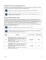
Menu
Item
Description
Choices / Ranges
Default Setting
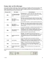
HA
High Ambient Temperature Limit —
Maximum ambient
temperature limit. Displayed and settable only in ºC. Should
the ambient temperature rise above the HA value, the audio
and visual alarms will activate and the compressor, heater,
fan, and pump will turn off.
NOTE:
Chiller’s rated cooling capacity is dependent on an
ambient temperature of 20°C (68ºF). Performance will
decrease as the ambient temperature rises. Continuous
operation at ambient temperatures above 40ºC (104ºF) is not
recommended.
+30 to 45ºC
Note: Always displayed
and set in °C
40ºC
FP
Maximum Fluid Pressure —
Maximum allowable fluid
pressure; settable in either PSI or kPa. Should the fluid
pressure rise above the maximum fluid pressure value, the
audio and visual alarms will activate and the compressor,
heater, fan, and pump will turn off.
NOTE:
The Chiller also incorporates a built in pressure
regulated bypass valve. It will maintain a maximum outlet
pressure by diverting flow of the process fluid to the reservoir.
The bypass valve may be adjusted by the customer.
CAUTION:
Maximum operating pressure for the Chiller is 100
PSI / 6.9 bar. Different pumps have different maximum
operating pressures.
10 to 100 PSI
69 to 690 kPa
(display value x 100)
80 PSI
5.5 x 100 =
550 kPa
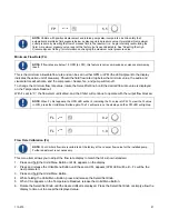
FL
Minimum Flow Rate
— Minimum allowable flow rate;
settable in either GPM or LPM. Should the fluid flow rate drop
below the minimum value, the audio and visual alarms will
activate, and the compressor, heater, fan, and pump will turn
off.
0 to 2 GPM
0 to 7.5 LPM
0.0 GPM
(0.2 GPM
optional)
0.0 LPM
(0.1 LPM
optional)
Fc
Flow Rate Calibration —
Allows adjustment of the displayed
flow rate to match that of a known standard.
0 to 99.9 gain
Nominal flow
AF
Auto-Refrigeration Set Point —
The upper temperature at
which the refrigeration system will activate; displayed and
settable in °C only. There will be no refrigeration or cooling at
set points above the AF setting.
No heater option
20° to 40°C
With heater option
20° to 50°C
No heater option
40°C
With heater
option
50°C
Cb
Compressor Band –
The temperature at which the
compressor will turn off. This protects the fluid temperature
from dropping too low during periods of low or no heat load.
The compressor turns back on when the temperature rises
above the set point.
-06° to -03°C
-06°C
°C
Calibration Offset
— Allows adjustment of the displayed
temperature to match that of an independent traceable
standard; displayed and settable in °C only.
±1.9°C 0.0°C
PC
Communications Baud Rate
— Selects the baud rate for
serial (RS232/RS485) communication.
24 (2400), 48 (4800),
96 (9600) or 192 (19200)
96
Содержание DCA203C4
Страница 1: ...Operator s Manual DuraChill Air and Water Cooled 2 and 3 HP Chillers 110 275 25 February 2015...
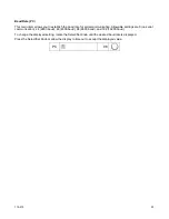
Страница 9: ...110 275 8 Rear View Power Switch Power Switch...
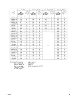
Страница 36: ...110 275 35 Pump Performance Specifications subject to change without notice...
Страница 40: ...110 275 39 Appendix Flow Diagram Air Cooled Chillers...
Страница 41: ...110 275 40 Flow Diagram Water Cooled Chillers...
Страница 42: ...110 275 41 Wiring Diagram 208 230V 1 Phase Air Cooled Chillers...
Страница 43: ...110 275 42 Wiring Diagram 208 230V 380 460V 3 Phase Air and Water Cooled Chillers...


