110-275
12
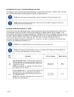
3. Set the Pressure / Flow Rate Display to read in either PSI or kPa (see
Normal Operation, Selecting the
Pressure / Flow Rate Display and Units
).
4. Remove the insulation covering the pressure regulating valve cap and then remove the cap. There may
be some coolant in the cap; this is normal.
5. Loosen the locknut and then using a flat blade screwdriver, adjust the pressure until the reading on the
Pressure / Flow Rate Display matches the desired maximum operating pressure. A clockwise rotation
increases pressure; a counter-clockwise rotation decreases pressure.
6. Set the minimum allowable flow rate to the desired value.
7. Tighten the locknut and replace the cap and insulation.
8. Set the Pressure / Flow Rate Display to the preferred reading (GPM, LPM, PSI, kPa).
Locknut
Содержание DCA203C4
Страница 1: ...Operator s Manual DuraChill Air and Water Cooled 2 and 3 HP Chillers 110 275 25 February 2015...
Страница 9: ...110 275 8 Rear View Power Switch Power Switch...
Страница 36: ...110 275 35 Pump Performance Specifications subject to change without notice...
Страница 40: ...110 275 39 Appendix Flow Diagram Air Cooled Chillers...
Страница 41: ...110 275 40 Flow Diagram Water Cooled Chillers...
Страница 42: ...110 275 41 Wiring Diagram 208 230V 1 Phase Air Cooled Chillers...
Страница 43: ...110 275 42 Wiring Diagram 208 230V 380 460V 3 Phase Air and Water Cooled Chillers...


