2-1
12H-M12M0-0309-0
CHAPTER 2
ELECTRICAL COMPONENTS
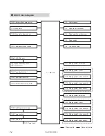
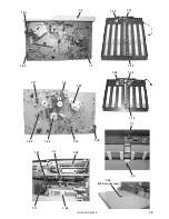
1. Block Diagram of Structure and Outline of
Each Block ...................................................... 2-2
1-1. MC Unit ................................................... 2-6
1-2. Control Panel .......................................... 2-6
1-3. Paper Feed Inlet Sensor ......................... 2-6
1-4. Paper Ejection Outlet Sensor ................. 2-6
1-5. Paper Switch ........................................... 2-6
1-6. Top Cover Switch ................................... 2-6
1-7. Side Cover Switch (DF-920 only) ........... 2-7
1-8. Paper Ejection Cover Sensor
(DF-920 only) .......................................... 2-7
1-9. Paper Feed Tray Upper Limit Detection
Switch (DF-920 only) .............................. 2-7
1-10. Paper Feed Tray Lower Limit Detection
Switch (DF-920 only) .............................. 2-7
1-11. Folding Plate 1 Set Switch ...................... 2-7
1-12. Folding Plate 2 Set Switch ...................... 2-7
1-13. Folding Plate 1 Index Sensor A/B ........... 2-7
1-14. Folding Plate 2 Index Sensor A/B ........... 2-7
1-15. Folding Plate 1 Home Sensor ................. 2-8
1-16. Folding Plate 2 Home Sensor ................. 2-8
1-17. Main Motor .............................................. 2-8
1-18. Paper Feed Tray Up/Down Motor
(DF-920 only) .......................................... 2-8
1-19. Folding Plate 1 Motor .............................. 2-8
1-20. Folding Plate 2 Motor .............................. 2-8
1-21. Stacker Roller Moving Motor .................. 2-8
1-22. Stacker Roller Home Sensor .................. 2-8
1-23. Paper Feed Clutch .................................. 2-8
1-24. Paper Ejection Clutch ............................. 2-9
1-25. Main Motor Index Sensor ........................ 2-9
1-26. PS P.W.B. Unit ....................................... 2-9
1-27. Paper Feed Tray Set Switch
(DF-915 only) .......................................... 2-9
1-28. Switching Power Supply ......................... 2-9
1-29. Power Switch .......................................... 2-9
1-30. Power Inlet .............................................. 2-9
1-31. Power Cord ............................................. 2-9
2. Errors and Causes ......................................... 2-10
2-1. When Paper Jams Occur ........................ 2-10
2-2. Troubleshooting ...................................... 2-10
2-3. Other Condition Messages ..................... 2-12
2-4. Emergency Measures When the Paper
Switch Damages ..................................... 2-14
3. Maintenance Mode ......................................... 2-15
3-1. Entering the Maintenance Mode ............. 2-15
3-2. Setting the Maintenance Mode ............... 2-15
3-3. List of Maintenance Modes ..................... 2-16
3-4. Precautions for Setting Folding Stopper
Fixed Mode (DF-920 only) ...................... 2-27
4. Backup Data Form ......................................... 2-28
5. Initializing the Memory .................................. 2-30
6. Precautions on Replacing the MC Unit ........ 2-31
7. Upgrading the Program Version ................... 2-32
8. Overall Schematic Diagram (DF-920) ........... 2-33
9. Overall Schematic Diagram (DF-915) ........... 2-34
10. Wiring Diagram 1/2 (DF-920) ......................... 2-35
11. Wiring Diagram 2/2 (DF-920) ......................... 2-36
12. Wiring Diagram 1/2 (DF-915) ......................... 2-37
13. Wiring Diagram 2/2 (DF-915) ......................... 2-38
Содержание DF-915
Страница 1: ...PAPER FOLDER DF 920 915 MAINTENANCE MANUAL ...
Страница 5: ...1 3 12H M12M0 0309 0 DF 915 Front view Operating side Rear view Drive side ...
Страница 95: ...12H M12M0 ...


