background image


Pt. No. 67385 


Issue 

1005 


Owners Manual


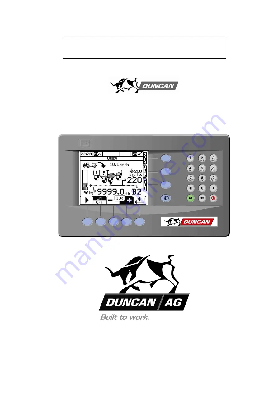
Duncan Drill 

Electric Drive System  


Head Office: 

Australian Branch: 

P.O. Box 2018 

4B Silverton Close 

Hilton Highway 

Laverton North 

Timaru, New Zealand 

Melbourne, Australia 

Telephone (03) 688 2029 

Telephone (03) 9314-9666 

Facsimile  (03) 688 2821 

Facsimile  (03) 9314-6810 

Содержание Enviro 3000e

Страница 1: ...6 Head Office P O Box 2018 Hilton Highway Washdyke Timaru New Zealand Telephone 03 688 2029 Facsimile 03 688 2821 Australian Branch 4B SIlverton Close Laverton North 3026 Melbourne Australia Telephone 03 9314 9666 Facsimile 03 9314 6810 From Serial Number 04200 ...

Страница 2: ......

Страница 3: ...r Loading 13 Magnetic Cut out Sensor 13 Transport Position 14 Coulter Penetration Depth 14 Double Disc Sowing Depth 14 Press Wheel Adjustment 14 Double Disc Scrapers 15 Press Wheel Scrapers 15 Level Drill 15 Electric Drive 15 Sowing Chart 16 Basic Calibration Procedure Setting Seeder Shutter Slides 17 Bottom Flap Setting 17 Seed Calibration 18 Calibration Deviations 19 Sowing Fine Seeds 20 Sowing ...

Страница 4: ...ld be allowed to use the equipment A separate illustrated parts section has been provided so that if any parts are required your dealer will be able to supply them by reference to part numbers The manual is considered as part of your machine and must remain with the machine when it is sold Right and left hand references in this manual are determined by standing behind the machine and facing in the...

Страница 5: ...ses automatically when the machine is raised into the transport position Working Principle The seed box slides seeder flaps and seeding rate are set to give the required seed delivery The front disc precuts the ground surface followed by the double disc which creates the seed bed Seed fertiliser is metered down the flexible convolute tubes from the boxes to the double disc unit and fed into the pr...

Страница 6: ...e for safety reasons where practical without compromising machine performance Ensure these are always fitted during operation Always exercise extreme caution in the vicinity of sharp edges and points Where possible guards are provided with the machine for safety reasons where practical without compromising machine performance Ensure these are always fitted during operation Footboards footsteps dra...

Страница 7: ... it Take careful note of all safety instructions both in this manual and on the machine itself Failure to comply with instructions could result in personal injury and or damage to the machine Replace missing or damaged safety signs on the machine and ensure that these remain clearly visible It is the owner s responsibility to ensure that anyone who operates adjusts lubricates maintains cleans or u...

Страница 8: ... machine Plan safe routes of travel and be aware of power lines and other roadside hazards Take particular care when towing implements on hillsides Do not ride or allow passengers on the machine This machine is not designed to carry passengers and no riders are permitted Road transport On public roads A speed of 40 km h must not be exceeded Do not operate during the hours of darkness unless standa...

Страница 9: ...or label for reference Avoid High Pressure Fluids Avoid any contact with fluids leaking under pressure because the fluids can penetrate the skin surface Any fluid which penetrates the skin will need to be removed immediately by a medical expert Seek specialist advice on this type of injury Relieve the pressure before disconnecting any hydraulic or other lines Make all repairs and tighten all fitti...

Страница 10: ...ression when dismantling or maintaining the machine It is recommended that you clean the machine with a water blaster or similar apparatus before commencing maintenance Make Sure the Machine is Well Supported When machinery is fitted with hydraulics do not rely on the hydraulics to support the machine During maintenance or while making adjustments under the machine always lock the hydraulics and s...

Страница 11: ...ne rather than specifically highlighting all possible hazards For safety decal locations on the machine refer Page 11 No Ride Passengers are not permitted anywhere on the machine Pinch Points Moving Parts Hazardous areas include Agitator drive units LH side Agitator shaft inside the boxes Seeder units box shaft and shaft connectors Adjacent dragbars and coulter arms Between double discs and other ...

Страница 12: ... areas Transport The two large wheels located at the rear of the machine are for the purpose of controlling maximum loading on dragbars and coulters These are also used to support the machine weight during transport Important Refer to safety cautions in the Transport section Page 12 of the manual Ensure that all linkage pins and security clips are fitted correctly Maintenance Refer Pages 24 28 for...

Страница 13: ...ecal Pt No Qty 1 No Ride 75 x 99 43906 1 2 Pinch Point Moving Parts 75 x 99 43907 6 3 Slippery When Wet 100 x 45 43902 2 4 Keep Clear 38 x 192 43909 2 5 Arrows 43905 4 6 Check Wheel Nuts Regularly 43708 2 7 40 km hr 43913 2 2 4 2 6 2 5 2 Enviro Inside Lid Table 2 Fig 2 1 3 2 4 7 7 ...

Страница 14: ...y the local Land Transport Authority or equivalent Braking when towing can cause the load to jackknife Use extra care when towing in adverse conditions such as mud inclines and sharp bends Lower towing speeds are recommmended on farm roads tracks and where one wheel is on or over a road verge 6 Attach safety chains to tractor Refer Fig 5 Safety chains must be crossed over underneath the coupling a...

Страница 15: ...d uneven sowing depth 2 Impact damage to a Ground engaging components b Bearings housings and axles c Fasteners structural components 3 More extreme conditions will result in greater vibration and uneven seed flow at low seeding rates Front Coulter Dragbar Loading The height of the drill when in the drilling position is determined by the laden weight and the number and size of the depth collars on...

Страница 16: ...ed down there are three holes 20mm apart for intermediate settings in which an M20 bolt can be fixed as a stop Choose the hole to give the best position An M20 bolt for this purpose is stored at the top front of each of the side plates Note The front coulter blades will sharpen with initial use and therefore penetration ability will improve Double Disc Sowing Depth The penetration depth of the dou...

Страница 17: ...l operating position and don t require adjustment before drill use Press Wheel Scrapers A minimum clearance of 2mm is recommended between the scraper and the press wheel Check the scraper clearance on full circumference regularly as press wheels can be eccentric Best scraper performance may be dependent on the ground conditions Level Drill Use the drawbar ram to tilt the drill so it is sitting lev...

Страница 18: ...2 3 41 457 5 2 73 SOWING RATES These are based on the maximum and minimum electric motor speeds which are independent of ground speed Recommended Settings Seed Type Shutter Bottom Metering Agitator 4 Calibration Slide 1 Flap 2 Wheel 3 Amount Grass Full 3 N E 1 0 kg Grass Mix Full 3 N E 1 0 kg Wheat 3 4 3 N E 2 0 kg Barley Full 3 N E 2 0 kg Oats Full 3 N E 2 0 kg Peas 3 4 3 N D 2 0 kg Kale 3 4 1 F ...

Страница 19: ...he various seed sizes require matching bottom flap clearances below the metering wheel The adjusting plate allows for 10 different settings The required position for the seed type may be found in the Sowing Chart The control levers are located on the LH end of the seedbox opposite end to the gearbox Number 1 corresponds to the minimum closed position and 10 the maximum gap Refer Fig 9 Fig 8 Fig 9 ...

Страница 20: ...Page 16 for hints on whether the agitator shaft should or should not be connected If it is to be disconnected remove the lynch pin Fig 11 1 5 For the test half fill the box with seed If this is not possible make sure the seed is evenly distributed over all seeders in the box 6 Now refer to the calibration procedures in the Electric Drive Operating Manual Note The amount of product to be dispensed ...

Страница 21: ...he basic setting of the bottom flaps should be checked at regular intervals When the flap handle setting is at 1 the clearance between the metering wheel and the flap should be set to 0 5mm Refer Fig 21 Page 28 Residues from the seed dressing on the bottom flaps and metering wheels can also influence the flowing properties of seed and hence the seed rate In such cases a balance will occur only aft...

Страница 22: ...x shaft clockwise until the holes of the fine seed wheel Fig 12 2 are visible Using the tool supplied Fig 13 1 disengage the the pin inside the hole so that the normal metering wheel rotates freely on the metering shaft At this time it would be advisable to close any shutter slides not required for the fine seed sowing When seed is to be sown again using the normal metering wheel press the pin fro...

Страница 23: ...sidue buildup on the flaps your calibration will now reflect accurately the required seed rate Note Remember to reconnect the agitator shaft as required for other seeds otherwise the consistency of seed rate will be affected Sowing Peas Peas having the size and shape as illustrated in Fig 15 e g White Field Peas can be sown without problems with all Duncan Drills with this type of metering wheel T...

Страница 24: ...22 Enviro 3000e Seed Drill Calibration Notes ...

Страница 25: ...23 Pt No 67303 Issue 0806 Enviro 3000e Seed Drill Calibration Notes ...

Страница 26: ...nect the alternator before attempting any welding See also the electric drive manual 2 Hydraulics Ensure hydraulic couplings male female are clean before connecting Dirty couplings will result in hydraulic oil contamination hydraulic cylinder seal damage and bore scores This in turn will result in oil leakage past the piston seals Filters are only fitted to the main wheel lines If hydraulic fittin...

Страница 27: ... Required 1 3 8 7 5 5 6 6 Fig 17 Fig 18 Table 4 Table 5 Pt No 67303 Issue 0806 The lubrication frequencies are only a guide Actual frequency will be dependent on extent of use and ground conditions For full list see Maintenance Schedule Page 26 Components Daily Weekly Pre season or after 20 ha or after 100 ha or 1000 ha Coulters Double Discs Press Wheels Seeders Agitators Bottom Flaps Wheel Tyres ...

Страница 28: ... hose clips Enviro 3000e Seed Drill Maintenance Schedule Table 6 Refer Maintenance Schedule Summary Chart Page 25 FRONT COULTERS D Check springs for damage breakage D Clean any dirt build up D Check discs for wear damage buckles etc D Check discs turn freely D Check discs for excessive sideplay 5mm W Check arms for damage sideplay W Check tightness of pivot pin end tab bolts W Check tightness of d...

Страница 29: ...unt of wear may be evident on the scrapers The scrapers should be reset using the adjusting bolt so they just touch the discs as described above Refer Fig 19 1 In some cases if a notch has formed on either of the blades by the abrasive action of the coulter disc you may need to regrind the leading edge to give optimum cleaning action or replace 3 Both Front Coulters Double Discs When replacing fon...

Страница 30: ... bottom flap can give way downwards A strong return spring Fig 21 4 brings the bottom flap immediately back into the working position The metering system should be checked every 100 hectares or weekly or before any sowing period with an empty seed box and empty metering housings Use the following proceedure Put the bottom flap setting levers located on the LH end of the seed boxes in position 1 fo...

Страница 31: ...ice Record DATE HECTARES REFER TO MAINTENANCE SCHEDULE FOR DETAILS Page 26 ANNUAL PRESEASON CHECK or every 1000 ha FRONT COULTERS DOUBLE DISCS PRESS WHEELS SEEDERS AGITATORS BOTTOM FLAPS WHEELS DRAWBAR COUPLING SAFETY CHAIN LIGHTS HYDRAULICS GENERAL SERVICED BY NOTES ...

Страница 32: ...30 Enviro 3000e Seed Drill Maintenance Notes ...

Страница 33: ...From Serial Number 04200 Head Office P O Box 2018 Hilton Highway Washdyke Timaru New Zealand Telephone 03 688 2029 Facsimile 03 688 2821 Australian Branch 4B Silverton Close Laverton North 3026 Melbourne Australia Telephone 02 9314 9666 Facsimile 02 9314 6810 ...

Страница 34: ......

Страница 35: ...raulics 10 Wiring Lighting Kit 12 Double Disc System 14 Front Disc Assembly 16 Double Disc Assembly 18 Radar System 20 Press Wheel Assembly 21 Seedbox Assembly 22 Agitator Drives 24 Seeder Assembly 26 Electric Drive 28 Enviro 3000e Seed Drill Parts List Contents ...

Страница 36: ...42 40 38 15 20 8 22 55 56 57 48 3 23 2 33 21 44 35 36 37 50 52 43 11 10 34 13 32 4 31 12 53 18 54 19 24 1 16 5 39 41 7 9 31 27 29 32 14 25 34 30 33 6 58 28 17 46 49 26 2 47 51 45 ...

Страница 37: ...nt 1 29 29100 Guard Rail Assembly 1601 Centres 1 30 29101 Guard Rail Assembly 796 Centres 1 31 29102 End Rail Assembly 2 32 29195 Calibration Tray Assembly 1427 2 33 29196 Calibration Tray Assembly 1297 2 34 29193 Ripstop Weather Skirt 2 35 45039 M16 x 45 Class 8 8 Zinc Plated Bolt 12 36 45140 M16 Nyloc Nut 12 37 45060S M20 x 40 Class 8 8 Zinc Plated Set Screw 8 38 45161 M20 Heavy Duty Flat Washer...

Страница 38: ...4 61 60 70 63 64 65 66 67 68 71 62 59 69 ...

Страница 39: ...oc Nut 4 61 45935 4 Ram RH Arm 1 62 43936 3 75 Ram LH Arm 1 63 29129 Wheel Sensor Mount Assembly 1 64 29134 Activator Arm 1 65 43956 Bar Magnet 1 66 45390 M8 x 75 Bolt 1 67 45137 M8 Nyloc Nut 1 68 43954 Hose Clamp 1 69 4800315 Hose Support 1 70 45181 M8 x 12 Socket Head Grub Screw 1 71 45157 M8 Heavy Duty Flat Washer 2 Pt No 67303 Issue 0806 ...

Страница 40: ...6 3 9 6 17 28 19 33 34 35 7 36 8 1 10 14 11 25 20 13 24 29 26 27 31 9 31 2 22 23 32 30 4 5 18 12 15 16 21 ...

Страница 41: ...ble Disc Beam Assembly 1 17 29021 Swivel Tow Hitch 1 18 29356 Decal Indicator Scale 1 19 29125 Ram Extension Indicator 1 20 29115 Nylon Coupling Pad 1 21 29290 Footboard Support Assembly 1 22 47462 1 1 4 Heavy Duty Flat Washer 2 23 45285 Dia 10 x 60 Roll Pin 2 24 45181 M8 x 12 S HD Grub Screw 1 25 45418S M10 x 25 Set Screw 1 26 45158 M10 Heavy Duty Flat Washer 1 27 45166 M10 Spring Washer 1 28 450...

Страница 42: ...8 Opposite Hand As Shown Note LH Only Shown 11 6 15 1 10 5 12 13 14 3 16 7 9 2 24 8 8 9 6 4 18 22 19 23 24 20 21 ...

Страница 43: ...eel Ram Pin 2 11 45018S M12 x 25 Set Screw 4 12 45418S M10 x 25 Set Screw 2 13 45166 M10 Spring Washer 2 14 45158 M10 Heavy Duty Flat Washer 2 15 45186 M10 x 12 Socket Head Grub Screw 4 16 43008 1 8 BSP Grease Nipple 4 18 43959 M18 x 1 5 mm Nut 6 19 43960 M18 x 1 5 mm x 61 mm Stud 6 20 43962 Dust Cap 1 21 43963 Castle Nut and Pin 1 22 43964 Taper Roller Bearing 32210 Small Outer 1 23 43966 Taper R...

Страница 44: ...5 10 1 3 10 2 24 4 16 8 9 21 7 23 25 19 12 27 32 30 14 17 26 23 22 25 20 11 6 10 Seal Kit for Item 1 Part No 43923 Seal Kit for Item 2 Part No 43922 Seal Kit for Item 14 Part No 43920 Slave Master All 6 hoses ...

Страница 45: ... 26723 Hydraulic Hose 2 80m 1 16 26724 Hydraulic Hose 2 50m 1 17 43496 3 4 UNO to BSPT Elbow 1 18 29322 Hydraulic Mounting Block Assembly 1 19 43280 3 4 UNO to 3 8 BSPP Nipple 1 20 29125 Ram Extension Indicator 1 21 29356 Indicator Scale Decal 1 22 29320 Double Hydraulic Tee Assembly 1 23 43937 1 5 x 4 x 3 4 Compact S Ram 2 24 29364 Hydraulic Hose 3 50m 2 25 29365 Hydraulic Hose 1 43m 4 26 22449 H...

Страница 46: ...12 5 6 ...

Страница 47: ... 9 43928 Trailer Connector 7 Pin Male 1 10 43929 Trailer Connector 7 Pin Female 1 11 45138 M10 Nyloc Nut 4 12 454185S M10 x 25 Class 4 6 Zinc Plated Bolt 4 13 45401S M6 x 16 Class 4 6 Zinc Plated Set Screw 8 14 45122 M6 Nyloc Nut 8 15 5W Festoon Bulb 15 x 44mm 4 16 21W Festoon Bulb 15 x 44mm 4 Enviro 3000e Seed Drill Wiring Lighting Kit Pt No 6730 Issue 0806 RH Side LH Side 2 8 9 8 3 4 11 12 13 14...

Страница 48: ...38 15 24 42 36 3 34 22 26 35 28 37 21 20 30 43 44 41 17 40 39 30 28 Disc Scrapers See Page 18 Press Wheel See Page 21 Discs Not Shown See Page 18 See Below See Below or or 3 4 6 12 34 35 5 11 8 7 8 11 13 37 20 26 1 14 21 28 15 21 19 or 33 4 19 2 ...

Страница 49: ... 29257 Jaw Lock Pin Assembly 1 17 29258 Spring Slide 1 18 23525 Spring 1 19 29263 Pivot Plastic Bush 1 20 29264 Pivot Bush 1 21 29265 Press Wheel Pivot Washer 2 22 10174 Press Wheel Spring 1 23 45321 5 16 D Shackel 3 24 29261 Press Wheel Arm Spacer 2 25 45055 M16 x 200 Grade 8 8 Bolt 2 26 45168 M16 Spring Washer 6 27 45043 M16 x 65 Grade 8 8 Bolt 1 28 45140 M16 Nyloc Nut 2 29 45443 M12 x 80 Bolt 1...

Страница 50: ...16 1 19 20 22 18 2 35 36 3 34 39 14 15 11 16 26 27 31 13 30 22 33 38 5 4 32 33 6 32 23 24 20 4 37 5 6 17 25 9 10 7 7 8 29 12 28 21 20 ...

Страница 51: ...45055 M16 x 200 Class 8 8 Zinc Plated Bolt 2 19 45043 M16 x 65 Class 8 8 Zinc Plated Bolt 1 20 45140 M16 Nyloc Nut 3 21 45037 M16 x 35 Class 8 8 Zinc Plated Bolt 1 22 45168 M16 Spring Washer 3 23 29212 M16 x 450 Eye Bolt 1 24 29214 Spring Cap 1 25 29215 Front Coulter Spring 1 26 29213 Clamp Side Plate Spacer 1 27 43953 Nylon Washer 2 28 29217 Plastic Pivot Bush 1 29 29219 Pivot Pin Cap 1 30 43899 ...

Страница 52: ...24 27 21 10 17 1 15 13 19 18 17 12 11 16 14 12 11 31 23 22 29 30 19 13 14 31 18 28 18 Scraper Assembly 26 20 Note Plastic Spacers Chamfer to the Inside Note Parts 29245 29246 items 12 17 may have been superseded by part 29241 ...

Страница 53: ...hread x 50 Disc Retaining Bolt 1 16 45040 M16 x 50 Class 8 8 Zinc Plated Bolt 1 17 29246 Bearing Sleeve 2 18 29247 25 i d x 35 o d x 1 6 Flat Washer 2 19 22136 Plastic Spacer 2 20 22086C RH Scraper Casting 1 21 22087C LH Scraper Casting 1 22 22088 Scraper Hinge Stainless 1 23 22069 Double Disc Scraper Mounting Strap 1 24 22070 Double Disc Scraper Tensioner 1 25 45404 M6 x 30 Class 4 6 Zinc Plated ...

Страница 54: ...29402 Radar Mount Bracket 1 4 29404 Radar Clamp Plate 1 5 45454 M12 x 300 Bolt 2 6 45139 M12 Nyloc Nut 2 7 45417S M10 x 25 Set Screw 3 8 45138 M10 Nyloc Nut 3 9 45411S M8 x 20 Set Screw 2 10 45151 M8 Light Flat Washer 2 11 45137 M8 Nyloc Nut 2 Enviro 3000e Seed Drill Radar System 1 3 2 7 9 5 4 6 8 10 11 ...

Страница 55: ...el 1 4 29259 Bearing Spacer 1 5 43939 Bearing 2 6 43895 Oil Seal 2 7 45024 M12 x 55 Class 8 8 Bolt 2 8 45139 M12 Nyloc Nut 2 9 45051 M16 x 130 Class 8 8 Bolt 1 10 45140 M16 Nyloc Nut 1 11 29266 Bearing Mount 2 12 43941 Tyre Spares 1 Enviro 3000e Seed Drill Press Wheel Assembly 10 12 2 7 2 3 4 6 9 5 Pt No 67302 Issue 0806 1 8 11 ...

Страница 56: ...6 15 32 17 21 29 17 21 29 19 27 27 19 31 19 27 31 19 27 14 43 30 7 28 21 38 36 38 26 36 26 9 8 28 21 32 29 21 22 5 40 33 6 41 33 Lid Hinge Detail Not Shown For Agitator Drive Detail Refer Page 24 Location Tab Detail Gas Strut Detail 15 29 44 45 21 46 48 47 46 48 29 21 20 34 35 5 ...

Страница 57: ...Hinge Pin Spring Clip 6 25 45852 No 8 x 3 8 Pan Pozi 23 Run Machines Only 4 26 45139 M12 Nyloc Nut 16 27 45702 4 8 x 9 5 Monel Pop Rivet 28 28 45758 M6 x 16 Zinc Plated Countersunk Pozi Drive Screw 4 29 45908 M6 x 16 Zinc Plated Pan Head Machine Screw 24 30 45186 M10 x 12 Socket Head Grubscrew 4 31 22485P Box Set Lifting Eye Profile 2 32 29119 Box Set Mounting Bracket 2 33 45185SS M10 x 10 Stainle...

Страница 58: ... Extension 2 10 43428 Nylon Bush 6 11 23633 Box Shaft Connecting Sleeve 2 12 22420 Agitator Shaft Joining Collar 2 13 45415 M8 x 45 Class 4 6 Zinc Plated Bolt 2 14 45416 M8 x 60 Class 4 6 Zinc Plated Bolt 2 15 45137 M8 Nyloc Nut 4 16 45180SS M8 x 10 Stainless Steel Socket Head Grub Screw 4 17 47615 6 x 40 Pipe Lynch Pin 4 Enviro 3000e Seed Drill Agitator Drives 1 2 3 4 5 13 14 6 15 7 15 8 9 10 10 ...

Страница 59: ...Box Set 2 7 29149 Agitator Joining Collar 1 8 43442 5 8 Lurethane Wiper Seal 2 9 45185SS M10 x 10 Stainless Steel Socket Head Grubscrew 2 10 45410SSS M8 x 16 Grade 316 Stainless Steel Set Screw 4 11 45137SS M8 Grade 316 Stainless Steel Nylock Nut 4 12 47600 M30 ISO Fine Zinc Plated Hex Lock Nut 2 13 45186 M10 x 12 Socket Head Grubscrews 2 Enviro 3000e Seed Drill Agitator Shaft Assembly Pt No 67303...

Страница 60: ...26 1 1 2 3 3 4 4 5 6 6 7 7 8 8 9 9 10 10 11 14 ...

Страница 61: ...Seeder Extension Funnel 1 7 22551 Seed Diverter 1 8 22548 Seeder Extension Spring Clip 1 9 43379 Seed Shaft Guide Bearing 1 10 43380 Guide Bearing Tension Spring 1 11 43382 Metering Wheel Clutch Hook 1 12 29270 Seed Fertiliser Conductor Tube 1 13 11102 No 42 Cray Clip 2 14 43362 Fine Seed Wheel Brush Optional 1 Enviro 3000e Seed Drill Seeder Assembly 12 12 13 13 8 7 6 Pt No 67303 Issue 0806 ...

Страница 62: ...28 4 3 1 13 15 16 11 17 7 5 8 6 2 9 14 12 12 11 10 10 11 12 Not Shown ...

Страница 63: ...rol Module 1000 1 10 43950 0 5m Priming Switch c w Connector 2 11 43949 0 5m Shaft Speed Sensor c w Connector 3 12 43948 0 5m Level Sensor c w Connector 4 13 43982 Duncan PS Instrument Lead 1 14 29376 Duncan 3000e 1 2 Box Harness 1 15 29377 Duncan 3000e Drill Harness to Tractor 1 16 43951 Radar 1 17 43956 Bar Magnet Wheel Ram Sensor 2 18 43958 Magnet Ring 1 per Box 19 45368SS M10 Starlock Fixing W...

Страница 64: ...30 2 2 1 8 9 2 5 5 3 4 3 4 6 6 7 3 10 7 ...

Страница 65: ...41 Gearbox Mount Assembly Front 1 2 45403S M6 x 25 Set Screw 10 3 45136 M6 Nyloc Nut 10 4 45156 M6 Heavy Duty Flat Washer 8 5 45434 M12 x 35 Bolt 4 6 45139 M12 Nyloc Nut 4 7 45159 M12 Heavy Duty Flat Washer 4 8 29142 Gearbox Mount Assembly Rear 1 9 29338 Priming Switch Bracket 2 10 45150 M6 Light Flat Washer 2 ...

Страница 66: ...32 Enviro 3000e Seed Drill Operator Notes ...

Страница 67: ...rill Electric Drive System Head Office Australian Branch P O Box 2018 4B Silverton Close Hilton Highway Laverton North Timaru New Zealand Melbourne Australia Telephone 03 688 2029 Telephone 03 9314 9666 Facsimile 03 688 2821 Facsimile 03 9314 6810 ...

Страница 68: ...1 ...

Страница 69: ...arm 24 B 5 4 Forward Speed Alarm 24 B 5 5 Motor Alarm 25 B 5 6 Motor Control Module Alarm 27 B 6 Calibration 29 B 6 1 Calibration Check Programme 1 29 B 6 2 Calibration Check Programme 2 30 B 6 3 Calibration Nudge Programme 32 C CONFIGURATION SETUP 35 C 1 Menu 35 C 1 1 Alarm Setup 35 C 1 2 Cal Check 36 C 1 3 Bin Setup 36 C 1 4 User Options 36 C 1 4 1 Speed Simulation 37 C 1 4 2 Display 39 C 1 4 3 ...

Страница 70: ...ALS screen part 20 Figure 20 TOTALS screen total 20 Figure 21 TOTALS screen 3 21 Figure 22 Low bin level alarm left 22 Figure 23 Low bin level alarm right 22 Figure 24 Low bin level alarm volume 23 Figure 25 Shaft confirmation alarm 23 Figure 26 Encoder alarm 24 Figure 27 Low speed alarm 24 Figure 28 High speed alarm 1 25 Figure 29 High speed alarm 2 25 Figure 30 Motor alarm 26 Figure 31 Motor spe...

Страница 71: ...Figure 58 HELPLINE screen 43 Figure 59 DRILL SETUP screen 44 Figure 60 INSTRUMENT SETUP screen 44 Figure 61 BIN CONFIG screen 46 Figure 62 BIN SETUP screen 47 Figure 63 DIAGNOSTIC screen 48 Figure 64 TEST ROUTINE screen 1 48 Figure 65 TEST ROUTINE screen 2 49 Figure 66 TEST ROUTINE screen 3 49 Figure 67 TEST ROUTINE screen 4 50 Figure 68 TEST ROUTINE screen 5 50 Figure 69 TEST ROUTINE screen 6 51 ...

Страница 72: ...and a tractor cab mounted console Connected to each bin is a seeder shaft confirmation sensor 2 low level sensors calibration priming switch electric motor complete with gearbox and a motor control module The console programming includes product information bin configuration and set up sowing rate set up calibration system monitoring etc A 2 System Schematic 2 Bin System A schematic of the complet...

Страница 73: ...tem is as follows This system connects directly to the 2 bin system above A 4 System Schematic 4th Bin System A schematic of the 4th bin system is as follows This system connects directly to the 2 bin system and the 3rd bin systems above using the Y junction shown below ...

Страница 74: ...7 A 5 Console Layout References are made throughout this manual to Keys A to I which correspond to the buttons labelled A to I above A B C D E F G H I KEYPAD ON OFF ENTER ...

Страница 75: ...ormat shown in Figure 1 the operator can use Keys E F to cycle through the list of products The application rate saved against that product will also be shown The letter shown in the graphic will also change to reflect the product selected Figure 1 BIN SETUP screen Key I can be used to move down the list with both ends of the arrow moving to indicate the product and bin selected Once at the end it...

Страница 76: ...e is a directory of 16 products and against each of these 4 factors are recorded These factors are rate step size alarm weight and calibration factor The 1st line simply reminds the operator which bin the product is set for The 2nd line is the product name This can be changed using the keypad pressing ENTER to confirm the name entered This new name then applies to any of the other bins that have t...

Страница 77: ...ere or on the INFO SETUP screen Doing a product calibration of this product on any bin overwrites this value irrespective of bin Pressing the ESC key returns to the BIN SETUP screen Pressing the ENTER key while showing the BIN SETUP screen accesses the RESET TOTALS screen See Figure 4 If Key I is pressed the instrument goes directly to the MAIN operating screen If Key E is then pressed a secondary...

Страница 78: ...he right hand bin is bin 2 rear The MAIN screen can be accessed at any time by pressing the MAIN button Key A Figure 5 2 bin configuration Figure 6 shows the MAIN screen display for one of the 3 bin configurations The left bin is bin 3 the small bin the middle bin is bin 1 and the right hand bin is bin 2 Figure 6 3 bin configuration 3rd box at front A B C D E F G H I A B C D E F G H I ...

Страница 79: ...e left bin is bin 3 the front small bin the left middle bin is bin 1 the right middle is bin 2 and the right hand bin is bin 4 the rear small box Figure 8 4 bin configuration Figure 9 shows a summary of the 4 bin configuration MAIN screen display This enables particular details of each bin to be displayed simultaneously The summary screens for the 2 bin and 3 bin configurations are the same except...

Страница 80: ...is out of work lifted a cross is shown a tick indicates in work lowered When the drill is out of work motor control and alarms will be inhibited The second line of the MAIN display advises the operator of the product that the details below relate to This will change when Key I is pressed The metering rolls will be stationary when the motors are stationary and as soon as the motors start rotating t...

Страница 81: ...oop The end of the arrow will move to indicate the bin currently selected underneath the metering roll The product rate amount hectares done and motor status shown will change with each bin Pressing Key H will turn the selected bin motor ON or OFF irrespective of whether the machine is in transport or not When turned off the product totals stop accumulating The key tab reverses shading to show the...

Страница 82: ...ithin the PRODUCT SETUP screen refer Figure 3 When a new product rate has been entered the MAIN screen shows the maximum forward speed for 3 seconds or until a Key has been pressed See Figure 13 The maximum forward speed shown is the corresponding ground speed when the motor is at maximum speed This is based on the product calibration factor Figure 13 MAIN screen max ground speed Keys F G are used...

Страница 83: ...duct remaining in the bin and also the shaft speed as calculated from the shaft confirmation sensor It is also used to access and set the bin contents and settings Figure 14 INFO screen 4 bin configuration Key I is used to cycle through the bins The end of the arrow also moves to the appropriate bin under the metering roll Pressing the INFO button Key B cycles between the individual and summary IN...

Страница 84: ...ting NOW and using the key pad and pressing ENTER Alternatively when a specific amount of product is being added to the bin select TO ADD and use the key pad and press ENTER to add to the NOW total The NOW total will be updated Pressing the ESC button Key G returns to the previous INFO screen Figure 16 BIN CONTENTS screen Pressing the SETUP button Key G when on the individual INFO screen accesses ...

Страница 85: ...alibration factor can be changed by using the keypad and pressing ENTER Pressing the CAL CHECK key tab when on the individual INFO screen accesses the first screen of the calibration check procedure For calibration programmes refer to B 6 1 Pressing the NUDGE key tab when on the individual INFO screen accesses the first screen of the calibration nudge programme For the calibration programme refer ...

Страница 86: ...h The fourth line shows the work rate for the last bout This is based upon the distance and time between the system going in to work and then going out of work It is updated every time the system goes out of work The fifth line shows the average work rate since the instrument was turned on that morning It is based upon the area covered and the time in work both shown above This information is rese...

Страница 87: ...Similar displays are shown for the 2 and 3 bin configurations The PART TOT key tab can be pressed to cycle through the PART and TOTAL registers Figure 19 shows the PART register screen while Figure 20 shows the TOTAL register screen Figure 19 TOTALS screen part Figure 20 TOTALS screen total Pressing the RESET key tab accesses the screen shown in Figure 21 This allows the reset to be accepted by pr...

Страница 88: ...21 being reset is that highlighted in the PART TOT key tab before the RESET key tab was pressed Figure 21 TOTALS screen 3 A B C D E F G H I ...

Страница 89: ... is uncovered The MAIN screen display changes the bin information of the bin which is low The alarm can be temporarily ignored by pressing the TARGET RETURN button Key E Figure 22 Low bin level alarm left Figure 23 shows the MAIN screen alarm display when the right hand low bin level is activated Figure 23 Low bin level alarm right Target Return A B C D E F G H I A B C D E F G H I ...

Страница 90: ... bin information of the bin which is low Figure 24 Low bin level alarm volume B 5 2 Shaft Confirmation Alarm Figure 25 shows the MAIN screen alarm display when the system is not receiving a signal from the shaft confirmation sensor The display defaults to the appropriate bin for the alarm The alarm can be temporarily ignored by pressing the TARGET RETURN button Key E Figure 25 Shaft confirmation a...

Страница 91: ... This alarm can not be ignored Figure 26 Encoder alarm B 5 4 Forward Speed Alarm Figure 27 shows the MAIN screen display if the drill is in work and the forward speed is below the minimum forward speed setting Refer to C 1 5 2 Figure 27 Low speed alarm Figure 28 shows the MAIN screen display if the drill speed exceeds the motors capacity to keep up The up arrows flash in sequence with the internal...

Страница 92: ...plication rate displayed is based on the maximum motor speed and the current forward speed Figure 28 High speed alarm 1 Figure 29 High speed alarm 2 B 5 5 Motor Alarm Figure 30 shows the MAIN screen display if there is no speed being registered from the motor but pulses are being received from the shaft confirmation sensor A B C D E F G H I A B C D E F G H I ...

Страница 93: ...e automatic motor overload alarm shutdown procedure is based on both the amount and the duration of the overload If the maximum operating current is only exceeded by a small margin then this is permitted for a short time before the alarm is initiated and the motor drive is shutdown If the current immediately exceeds the threshold by a large amount then the alarm is instantly shown and the motor dr...

Страница 94: ...rload alarm shutdown action will be recorded on the instrument Stop the drill and lift it into the transport position the alarm shutdown is then automatically reset Check for the cause of the overload shutdown e g faulty bearing seed bag wrapped around agitator shaft etc Assuming the problem is rectified the operator may then continue working by lowering the drill into work If the alarm re occurs ...

Страница 95: ...28 Figure 33 Motor control module offline A B C D E F G H I ...

Страница 96: ...roduct to be dispensed This is done by using the key pad and pressing ENTER The programme gives the option to correct the amount to be dispensed If the number entered is incorrect use the keypad and press ENTER If the number was correct press ENTER to proceed to the next screen Figure 34 CAL CHECK screen 1 1 The second screen is shown if Figure 35 Pressing ENTER again will start the product dispen...

Страница 97: ...d and new calibration factors and the percentage error as shown in Figure 37 Press ENTER to accept the change or ESC to exit the programme without changing Figure 37 CAL CHECK screen 1 4 B 6 2 Calibration Check Programme 2 The programme 2 calibration is essentially the same as programme 1 however it is activated using the priming switches mounted into the left hand side plate of the machine A B C ...

Страница 98: ...this programme the option of entering the weight to be dispensed is not available The product starts being dispensed into the calibration trays immediately Figure 38 CAL CHECK screen 2 1 The product being dispensed accumulates until the priming switch is pressed a second time for second and released The screen display changes to that shown in Figure 39 Figure 39 CAL CHECK screen 2 2 A B C D E F G ...

Страница 99: ...secondly two bins can be calibrated simultaneously When calibrating two bins simultaneously press the priming switch for the first bin and release after second to start product dispensing Press and hold the priming switch for second for the second bin The console will display the product weight accumulating of the bin started last When both bins are finished dispensing the console will display and...

Страница 100: ...o enter the actual weight the weight of product that has been dispensed and press ENTER Figure 42 NUDGE screen 2 The last screen as shown in Figure 43 shows the old and new calibration factors and the error If the error value is negative the system has not applied as much as it should have The calibration factor will decrease to increase the motor revolutions Press ENTER to accept the correction o...

Страница 101: ...34 Figure 43 NUDGE screen 3 A B C D E F G H I ...

Страница 102: ...by pressing Key D Items on this list can be accessed by using the keypad See Figure 44 Figure 44 MENU screen C 1 1 Alarm Setup From the MENU screen press Key F to access the ALARM SETUP screen as shown in Figure 45 Figure 45 ALARM SETUP screen A B C D E F G H I A B C D E F G H I ...

Страница 103: ... exit the ALARM SETUP screen and return to the MENU screen C 1 2 Cal Check From the MENU screen press the CAL CHECK button Key G to access the first screen of the calibration programme 1 Refer to section B 6 1 This calibration programme is also accessible by pressing INFO SETUP CAL CHECK C 1 3 Bin Setup From the MENU screen press the BIN SETUP button Key I accesses the BIN SETUP screen shown Figur...

Страница 104: ...e SIM button Key E when on the USER OPTIONS screen accesses the SIMULATED SPEED screen See Figure 48 The electric drive system can be driven at a set speed simulated speed rather than being dependent on the true ground speed sensor radar This is useful if there is a radar failure The speed can be changed by using the up down arrows or the keypad and pressing ENTER Figure 48 SIMULATED SPEED screen ...

Страница 105: ...See Figure 52 When the simulated speed is running it is shown on the MAIN screen as shown in Figure 49 The screen flashes between the two displays until the speed is cancelled Figure 49 MAIN screen with SIMULATED SPEED To cancel the simulated speed press the SIM OFF button Key E on the USER OPTIONS screen shown in Figure 50 A B C D E F G H I A B C D E F G H I ...

Страница 106: ...for setting the brightness and contrast Use appropriate arrows to select and adjust Use ESC key to return to the USER OPTIONS screen Figure 51 DISPLAY screen C 1 4 3 Forward Speed Sensor The SPEED FACTOR screen shown in Figure 52 is for setting the true ground speed sensor radar This can be set manually if the figure is known by using A B C D E F G H I A B C D E F G H I ...

Страница 107: ...Figure 53 The programme requires to operator to drive 100m For accurate results measure out 100m and ensure the drill is sitting level with the ground before starting Figure 53 SPEED FACTOR CALIBRATION screen 1 Pressing the ENTER key on the keypad starts the routine and the display changes to the screen in Figure 54 After the operator starts driving the screen changes to as shown in Figure 55 As t...

Страница 108: ... FACTOR CALIBRATION screen 2 Figure 55 SPEED FACTOR CALIBRATION screen 3 After stopping press the ENTER key One of the screens in Figure 56 will appear If the factor it calculates is greater than 0 05 then the left hand screen will be displayed otherwise the right hand screen will be displayed A B C D E F G H I A B C D E F G H I ...

Страница 109: ...SC button can be pressed at any time to stop the calibration and return the SPEED FACTOR screen C 1 4 4 Time Date Figure 57 shows the TIME DATE screen These can be changed by using the up down arrows to select the required line using the keypad to enter the correct figure and pressing ENTER The ESC key can be pressed at any time to return to the USER OPTIONS screen A B C D E F G H I A B C D E F G ...

Страница 110: ...he name address number as required Figure 58 HELPLINE screen C 1 5 Drill Setup From the MENU screen enter 2 using the keypad to access the DRILL SETUP screen See Figure 59 The default pin number to access the DRILL SETUP is 6789 These setting are generally specific for the machine configuration and will not require changing Note TODAY totals will reset at midnight so it is important that the time ...

Страница 111: ...ecimal places maximum 9 999m C 1 5 2 Instrument Setup Figure 60 shows the INSTRUMENT SETUP screen Figure 60 INSTRUMENT SETUP screen On this screen the operator can change the configuration of the Area cut out on the Pro Series Default setting is In work If there is a sensor or harness failure the setting can be changed to Out of work so the operation can continue until the sensor repairs are done ...

Страница 112: ...arms Max Motor Cur refers to the maximum motor current When the motors operating current exceeds this amount for a specific amount of time then an alarm is initiated and the motor stopped C 1 5 3 Bin Configuration There are four different bin configurations All bin configuration options available in the BIN CONFIG screen are shown in Figure 61 A B C D E F G H I A B C D E F G H I ...

Страница 113: ... at the front or rear Where there are 2 small bin fitted the third box is at the front an the fourth bin is at the rear The bin configuration can be changed by using the across arrows C 1 5 4 Bin Setup Figure 62 shows the BIN SETUP screen where the settings for the gearbox ratio maximum motor speed and pulses received per metering shaft revolution These are all factory settings and must not be cha...

Страница 114: ... factor is the maximum motor speed This is used to calculate the maximum forward speed that any application rate set into the system can be achieved The third factor is the shaft sensor pulses per revolution This is used to calculate the shaft speed correctly Press ESC to exit the BIN SETUP screen and return to the DRILL SETUP screen C 1 6 Diagnostics From the MENU screen enter 3 using the keypad ...

Страница 115: ... to access the first TEST ROUTINE screen shown in Figure 64 Figure 64 TEST ROUTINE screen 1 This requires the machine to be fully raised to fully extend the wheel rams If the system is sensing a change in the area cut out sensor the display will automatically change to the second screen See Figure 65 If there is no change sensed the display will automatically change after 30 seconds A B C D E F G ...

Страница 116: ...ee Figure 66 If there is no change sensed the display will automatically change after 30 seconds Figure 66 TEST ROUTINE screen 3 The third screen requires the operator to wave a hand in front of the true ground speed sensor radar If the system receives a signal the display will automatically change to the third screen See Figure 67 If there is no signal the display will automatically change after ...

Страница 117: ...gnal from the shaft confirmation sensors After the motors stop the display will automatically change to the fifth screen See Figure 68 Figure 68 TEST ROUTINE screen 5 The fifth screen requires the operator to cover all bin sensors and press each priming switch for 2 seconds This can be done in any order When the first signal is received the display automatically changes to the sixth screen See Fig...

Страница 118: ...ummary of the test routine Items with a X highlight a fault This could be in the switch or sensor itself or in the wiring Figure 70 TEST ROUTINE screen 7 Pressing ENTER in the keypad returns the display to the DIAGNOSTIC screen C 1 6 2 Instrument Live The screen shown in Figure 71 shows the supply voltage the status of the cut out input how many motor control modules are connected and how many A B...

Страница 119: ...t any time to return to the DIAGNOSTIC screen C 1 6 3 Motor Module 1 Live Figure 72 shows a typical live screen of the Motor Control Module bin 1 diagnostic Figure 72 MCM 1 LIVE screen 1 The 1st line of the display shows the status of the motor drive on or off and the current being drawn by the motor A B C D E F G H I A B C D E F G H I ...

Страница 120: ...y of the forward speed input The 6th line shows the actual forward speed as calculated from the frequency above and the Speed Sensor Factor See Figure 52 The 7th line of the display shows the status of the shaft confirmation input and also the timer for closure The 8th line of the display shows the status of the priming switch and also the timer for closure Pressing the down arrow then changes the...

Страница 121: ... Int Temp refers to the voltage on the internal temperature sensor fitted to the heat sink in the motor control module Below this the calculated temperature Pressing the up arrow then changes the screen to display the initial information or the ESC can be pressed to return to the DIAGNOSTIC screen ...

Страница 122: ... that the drill has covered This is based on speed width and c o status It cannot be reset unless a POR is carried out The 2nd line of the display is working hours This accumulates when any of the motors are operating By using the up down arrows and pressing ENTER the history screen for each motor control module can be accessed Figure 75 shows the display for MCM1 A B C D E F G H I ...

Страница 123: ...hen the motor is operating The 2nd line shows the time of motor operation The 3rd line shows the number of motor revolutions The 4th line shows the offline count This number increases by 1 everytime the module is recognised as being offline Pressing the ESC key returns to the HISTORY screen A B C D E F G H I ...

Страница 124: ...l bins Shaft Sensor 3 0 ppr all bins Product Name Rate kg ha Step Alarm Weight Kg Cal factor kg rev A Grass 20 5 5 0 280 B Grass Mix 20 5 5 0 300 C Wheat 80 5 10 0 700 D Barley 80 5 10 0 690 E Oats 80 5 10 0 690 F Peas 80 5 10 1 000 G Kale 10 5 2 0 092 H Rape 10 5 2 0 090 I Swedes 5 0 5 1 0 093 J Turnip 5 0 5 1 0 093 K Lucerne 15 5 3 0 100 L W Clover 5 0 5 1 0 094 M R Clover 5 0 5 1 0 094 N Urea 8...

Страница 125: ...or replace as necessary Fuse blown Tractor or drill power leads have mechanical damage or have short circuited Motor damage Blocked seeder s or agitator Motor overload Repair or re insulate power lead Press each priming switch and check each motor is operational Check for obstructions causing abnormal loading If running small seeds disconnect agitator shaft Motors are not operating Motors are turn...

Страница 126: ...or replace as necessary Motors operates at maximum speed Poor motor encoder connection with drill harness Harness faulty Check connection Check continuity of drill harness and repair or replace as necessary Application rate is incorrect Application rate Calibration factor Obstruction Forward speed sensor Sowing width Check setting Recalibrate product Check for and remove obstruction Check setting ...

Страница 127: ...ow level alarm to 0kg Bin contents is low sensor is uncovered and more product needs to be added or turn alarm setting to off Replace sensor with a known working sensor if the replacement sensor works the original sensor is faulty Priming switch not functioning Faulty sensor Connect another priming switch if functioning correctly then original switch is faulty Shaft confirmation alarm sound contin...

Страница 128: ...the drill is in the working position Area cut out sensor Access the INSTUMENT SETUP screen and change the area cut out setting from In Work to Out of Work Seeders will dispense seed relative to travel speed regardless of whether the drill is in the working position or in the transport position To stop the seeding operation turn the motors or the console off Priming switch Initiate the calibration ...

Страница 129: ...____________________________________ _____________________________________________________________________ _____________________________________________________________________ _____________________________________________________________________ _____________________________________________________________________ _____________________________________________________________________ _____________...

Страница 130: ...___________________________________________________________________ _____________________________________________________________________ _____________________________________________________________________ _____________________________________________________________________ _____________________________________________________________________ ____________________________________________________...

Отзывы: