STP Lite User Manual Revision 1.02
STP Lite
'Smart Terminal Plus' Lite
Stand Alone GSM/GPRS Multi-Purpose Controller
with Logic Flow Lite Configuration Software
User Manual
Revision 1.02
Страница 1: ...STP Lite User Manual Revision 1 02 STP Lite Smart Terminal Plus Lite Stand Alone GSM GPRS Multi Purpose Controller with Logic Flow Lite Configuration Software User Manual Revision 1 02...
Страница 2: ...9 Duetech Beres Ltd All rights reserved The copyright and proprietary rights in the guide belong to Duetech Beres Ltd It is strictly forbidden to copy duplicate sell lend or otherwise use this guide i...
Страница 3: ...lling the Digital Input 24 Connecting the Power Supply 25 SECTION 3 3 STP OPERATION 27 Status LEDS 27 Reset Button 29 CHAPTER 4 USINGLOGICFLOWLITE 30 SECTION 4 1 GETTING STARTED WITH LOGIC FLOW LITE 3...
Страница 4: ...ction List 59 SECTION 4 7 WRITING LOGIC TO THE DEVICE 59 Procedure for Writing the Instructions to the STP 59 Troubleshooting a Failed Write to the STP Lite 60 SECTION 4 8 SOME USEFUL EXAMPLES 61 Find...
Страница 5: ...nd examples of using the Logic Flow Lite interface Section 1 2 Uses of the STP Lite The STP Lite owes its name to the fact that it employs a minimal number of inputs and outputs However this poses no...
Страница 6: ...e The warning symbols you will encounter in the manual have the following meaning DANGER Indicates warning of possible danger to the life and health of the user if the relevant safety measures are not...
Страница 7: ...t which allows you to make the STP Lite send a report to you via Serial Communication RS232 This way the user can create Word Excel reports based on the data from the STP Internal Li Ion rechargeable...
Страница 8: ...ollowing General Description Hardware Description Section 2 1 STP Lite General Description The STP Lite is a stand alone multipurpose terminal with extended logic control with cellular capabilities Th...
Страница 9: ...STP Lite User Manual Revision 1 02 10 Figure 2 Side View of the STP Lite Showing Dimensions...
Страница 10: ...will reject the incoming call and only use the Caller ID if needed RS232 An RS232 message from any capable device for example a computer or a PLC In addition there are four other input events that the...
Страница 11: ...trol tasks SMS An SMS message to your mobile phone GPRS A GPRS message to your TPC IP Internet server OUTGOING CALL Outgoing call to a predefined phone number The STP Lite will make the call and hang...
Страница 12: ...summary of the hardware the STP Lite employs Packaging The STP Lite is packaged in a small 72 x 90 x 50 mm polystyrene case The casing allows for a DIN rail mount to insure ultimate safety and stabili...
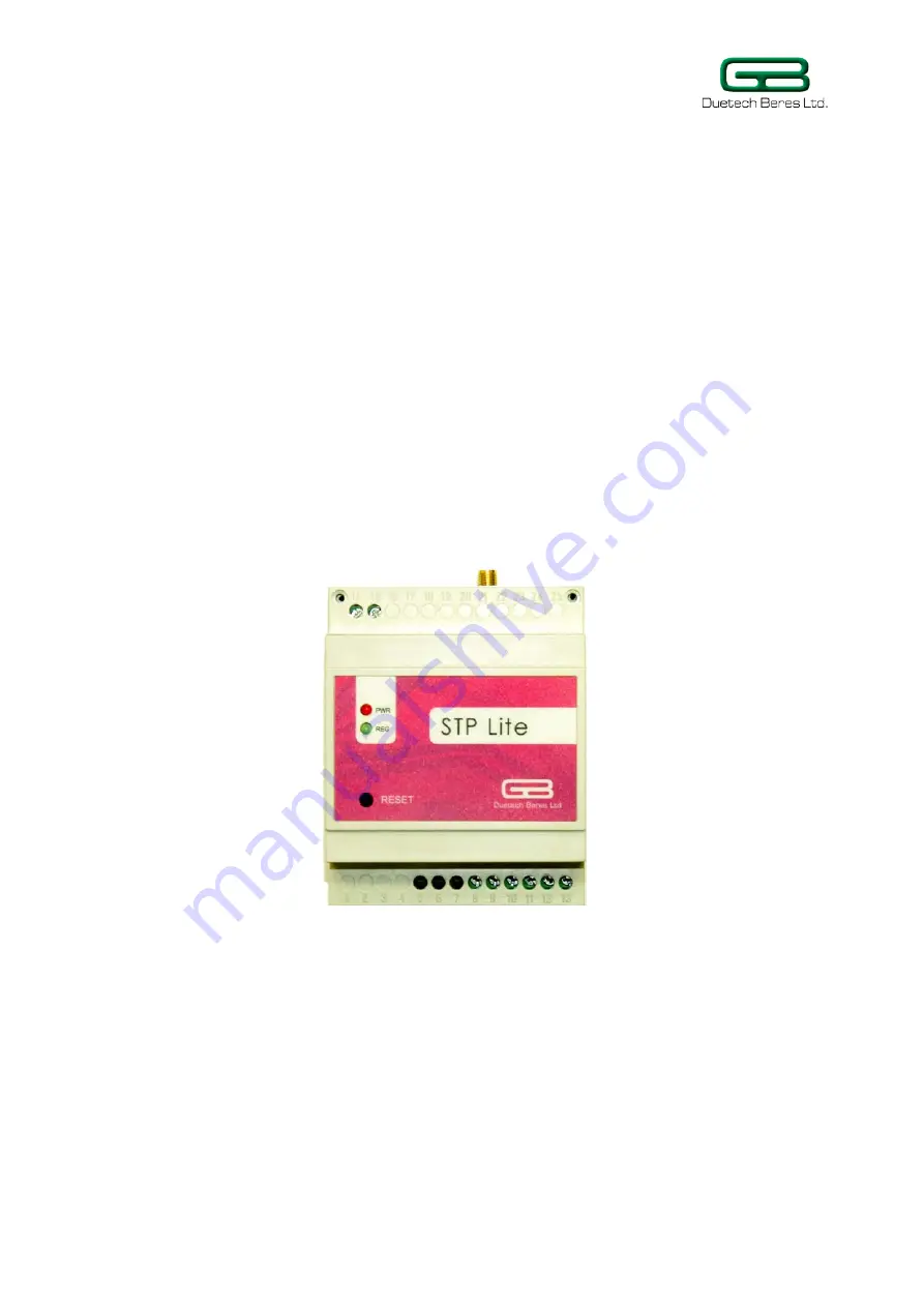
Страница 13: ...unicates with the STP Lite to write the commands from the serial port on your computer to the STP Lite Indication LEDs The STP Lite has two indicator LEDs a red LED indicating power supply to the devi...
Страница 14: ...ow The table lists the contents of the kit and their part numbers Table 3 Package Contents Part Description QTY P N STP Lite Controller Unit 1 STPL0001 Power Supply 12 V DC Voltage Transformer 1 PS220...
Страница 15: ...tput a 6 mm wide Phillips or flathead screwdriver will do Mounting the STP Lite Unit Mount the STP Lite by pushing or snap fitting it onto a DIN rail top hat rail 35 mm Pull out the black tab on the S...
Страница 16: ...must only be used in rooms that are dry and clean Protect the device from humidity water or heat The device must not be used in environments containing flammable gases fumes or dust Do not subject th...
Страница 17: ...device Installing the SIM Card Open the STP Lite casing by gently pushing in the two tabs at the top where the GSM Antenna is attached or bottom where are the attachments for the digital output and in...
Страница 18: ...NO Relay Output Digital Input Figure 9 Input Output side view of STP Lite unit Place a SIM card in the SIM card holder Figure 10 Inside of STP Lite unit showing the slot for the SIM card SIM Card Slo...
Страница 19: ...M is sensitive to electrostatic discharge If you are installing a used SIM card insert the SIM in a mobile phone first to ensure that the SIM doesn t contain any saved SMS messages These messages may...
Страница 20: ...e adapter Attaching the Relay Output The Smart Terminal Plus Lite has one relay dry contact output The output can be configured as either Normally Open NO or Normally Closed NC The other lead of the r...
Страница 21: ...C Common Hole 11 NO Normally Open Connects the circuit when the relay is activated Disconnects when the relay is inactive The STP Lite device can be used to control digital output In the following ill...
Страница 22: ...y output The Lamp is connected to the Normally Open terminal block and the power source for the lamp is connected to Common Upon receiving the digital input the relay output s Normally Open terminal w...
Страница 23: ...must be within the range 0 24 V DC ATTENTION Be certain not to exceed the maximum input voltage of 24 V DC Exceeding this value may cause irreparable damage to the STP Lite unit Figure 16 Input Output...
Страница 24: ...between 9 24 V DC The STP Lite kit contains a transformer that converts the wall current to 12 V DC The connector has two bare wires one to be connected to the negative terminal and one to the positiv...
Страница 25: ...e power supply lead from transformer ATTENTION Ensure the correct polarity of the power supply terminals If using another DC voltage source be certain not to exceed 24 V This will cause irreversible d...
Страница 26: ...Lite Red PWR LED After applying the 12 V DC power supply or inserting the back up battery check that the red PWR LED lights up The red PWR LED indicates that the main power is applied or that the back...
Страница 27: ...ular network A lower pitched beep then indicates that the device is connected and functioning and the green LED subsequently flashes periodically During normal functioning of the device the green LED...
Страница 28: ...encounter a problem with the functioning of the device use the Reset button on the front of the device to reset the STP This will allow you to restart the device without having to detach it from the...
Страница 29: ...figuring and using the Logic Flow Lite Software that comes with the STP Lite unit Section 4 1 Getting Started with Logic Flow Lite When you click on the Logic Flow Lite Platform icon on your desktop o...
Страница 30: ...and displays it on the screen included in future release Erase Device Erases the logic that has been written to the device included in future release STP Lite Toolbar Commands Logic Flow Lite Command...
Страница 31: ...rvice providers that require it maximum 18 characters User name that was configured in the SIM CARD maximum 18 characters Password that was configured in the SIM CARD maximum 18 characters To set the...
Страница 32: ...communication between your computer and the STP Lite device 2 If there are several serial ports on your computer select the appropriate one from the drop down list near Port and type in the Baud Rate...
Страница 33: ...Settings Spreadsheet is what allows you to assign an identifying name to each STP Lite unit In the UNIT ID field type the desired name for your particular STP Lite unit When the STP Lite unit will sen...
Страница 34: ...tput event execution similar in function to DISARM command see p 44 DISARM Input Event Configuration Settings Commands Read Configurations from Device This allows you to read the device s configuratio...
Страница 35: ...STP Lite Adding a Number to the Phonebook To add a number to the Phonebook 1 Click the Phonebook command in the Logic Flow Lite opening screen The Phonebook window will open 2 Click Add The Phone Num...
Страница 36: ...added will not be saved in your computer In order to save the phone number and name click on Save Close Logic Flow Lite saves the Phonebook data locally on your computer and updates the STP Lite as s...
Страница 37: ...ook To be implemented in future release Section 4 4 Setting the STP s Input Event For the STP Lite to implement condition sentences you must program the input and output events of the device The Logic...
Страница 38: ...han one output event click on Add Output Event The Add Condition window will expand to accommodate another Output Event 3 If you choose to remove one of the output events click on Remove this event He...
Страница 39: ...you press reset or write to the STP Digital Input Event As mentioned before the STP Lite takes one digital input If the input voltage is between 1 2 24 V the input is considered HIGH If the input volt...
Страница 40: ...Event is designed for this purpose To set Main Power as an input event 1 Click on the arrow near the Input event drop down list box and select the Main Power input event 2 Select in the list box next...
Страница 41: ...he possible senders of an incoming SMS message to the device Select ALL to allow all SMS senders to activate the STP Lite by sending the specified SMS message to the device Select GROUP to allow only...
Страница 42: ...ect ALL to allow all callers to activate the STP Lite by calling the device Select GROUP to allow only callers whose phone numbers are listed in your Phonebook to activate the STP Lite by calling the...
Страница 43: ...n the STP Lite is used for security or alarm system Let s say you want to set an alarm only after you leave the area you wish to secure Setting the input of the STP Lite to DISARM will cancel all outp...
Страница 44: ...STP Lite User Manual Revision 1 02 45...
Страница 45: ...order to access the device see Section 4 8 Some Useful Examples p 61 To use the STARTUP option as input to the STP Click on the arrow near the Input event drop down list box and select the STARTUP inp...
Страница 46: ...ered GPRS Sends a GPRS message from the STP Lite when triggered RS232 Sends a text RS232 message to the Logic Flow Lite interface when the STP Lite is triggered OUTGOING CALL Initiates an outgoing cal...
Страница 47: ...ration Seconds box set the duration for the output to be either opened closed or to toggle You have two options to specify the output s duration Type in the number of seconds desired for the output ev...
Страница 48: ...t 1 Click on the arrow near the Output Event list box and select TIMER1 TIMER2 TIMER3 or TIMER4 The following screen capture has all the timers employed as output events 2 In the SET box type in the t...
Страница 49: ...umber the number that is to receive an SMS message from the STP Lite device in the To field You can either Manually enter a phone number in the field or Click on the arrow near the To field to select...
Страница 50: ...2 Supply the IP or the domain name and Port in the To text box The format for the IP PORT combination is IP ADDRESS PORT for example 192 168 1 1 1023 where 192 168 1 1 is the IP Address and 1023 is th...
Страница 51: ...l in the message text on the Output Message text box 3 Click OK Outgoing Call Output Event You can have the STP Lite send you an outgoing call as the output event When the STP Lite receives the specif...
Страница 52: ...an use this for example to turn off an alarm that has been triggered by a previous input event To make RESET as the output event for the STP 1 Click on the arrow near the Output Event list box and sel...
Страница 53: ...upon receiving the specified input event 3 Click OK Alarm Output Event You can use the STP Lite device as an alarm When you set ALARM as the output event the STP Lite will emit a high pitched alarm so...
Страница 54: ...lar STP Lite device you might want to save it for later use For example if you move the STP Lite unit temporarily to a different circuit you will want to restore the previous set of instructions when...
Страница 55: ...1 02 56 The Save As dialog box will open prompting you to give a name to your compilation of instructions Supply a name in the File name box and click Save The list of instructions will be saved as a...
Страница 56: ...nd corner of the Logic Flow Lite opening screen Also the instructions from the condition file you selected will appear on the Logic Flow Lite Screen Removing instructions from the list Logic Flow Lite...
Страница 57: ...ove The selected condition will be erased from the display Editing the Instruction List If you want to modify one of the instructions to the STP Lite Logic Flow Lite has a convenient editing feature T...
Страница 58: ...d All To collapse all the instructions click on Collapse All To expand an individual instruction click on the symbol next to the input event To collapse an expanded item click on the symbol next to th...
Страница 59: ...was successful you will receive the prompt Flash Success Troubleshooting a Failed Write to the STP Lite If the write to the device was not successful you will receive a warning box prompting you eith...
Страница 60: ...icates that the device has been restored to the Startup state In Startup state you will have to press Reset to attempt the above procedure again If the problem persists contact Technical Support Secti...
Страница 61: ...Flow Lite opening screen click on the Add Condition command 2 Set the Logic Flow Lite input event as SMS and type in the SMS message you wish to send the STP Lite 3 Set the output event as DISARM and...
Страница 62: ...mand 5 Set the Logic Flow Lite input event as TIMER1 and the Output Event as ALARM and click OK The second line of the command to the STP Lite will appear on the screen 6 Click on Write Logic to Devic...
Страница 63: ...1 In the Logic Flow Sense opening screen click on the Add Condition command 2 Set the Logic Flow Sense input event as SMS and type in the SMS message you wish to send the STP Sense 3 Set the output ev...
Страница 64: ...thing is connected flawlessly Problem No 2 Can t send receive calls SMS GPRS When you have a trigger response that needs to send an SMS or make a call or send a GPRS message and you aren t receiving...
Страница 65: ...green led is constantly on instead of blinking Solution suggestions Check the connection of the antenna If your SIM card is protected with a pin code you need to enter the code in the configuration wi...
Страница 66: ...information about our products recommendations for accessories components online documentation and updates please visit our website www duetech gberes com Revision History Date Rev Author 16 04 09 In...