Duerkopp Adler 4180i-1 Скачать руководство пользователя страница 4

1

1. General safety instructions

The  non-observance  of  the  following  safety  instructions  can  cause  bodily  injuries  or  damages  to  the  machine.

1. The machine must only be commissioned in full knowledge of the instruction book and operated by persons with appropriate

training.

2. Before  putting  into  service  also  read  the  safety  rules  and  instructions  of  the  motor  supplier.
3. The  machine  must  be  used  only  for  the  purpose  intended.  Use  of  the  machine  without  the  safety  devices  is  not  permitted.

Observe  all  the  relevant  safety  regulations.

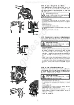
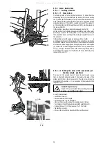
4. When  gauge  parts  are  exchanged  (e.g.  needle,  top  roller,  needle  plate,  feed  dog  and  bobbin)  when  treading,  when  the

workplace  is  left,  and  during  service  work,  the  machine  must  be  disconnected  from  the  mains  by  switching  off  the  master

switch  or  disconnecting  the  mains  plug.

5. Daily  servicing  work  must  be  carried  out  only  by  appropriately  trained  persons.
6. Repairs,  conversion  and  special  maintenance  work  must  only  be  carried  out  by  technicians  or  persons  with  appropriate

training.

7. For service or repair work on pneumatic systems the machine must be disconnected from the compressed air supply system.

Exceptions  to  this  are  only  adjustments  and  function  checks  made  by  appropriately  trained  technicians.

8. Work  on  the  electrical  equipment  must  be  carried  out  only  by  electricians  or  appropriately  trained  persons.
9. Work  on  parts  and  systems  under  electric  current  is  not  permitted,  except  as  specified  in  regulations  DIN  VDE  0105.

10. Conversions  or  changes  to  the  machine  must  be  authorized  by  us  and  made  only  in  adherence  to  all  safety  regulations.
11. For  repairs,  only  replacement  parts  approved  by  us  must  be  used.
12. Commissioning  of  the  sewing  head  is  prohibited  until  such  time  as  the  entire  sewing  unit  is  found  to  comply  with  EC

directives.

It  is  absolutely  necessary  to  respect  the  safety  instructions  marked  by  these  signs.

Danger  of  bodily  injuries  !

Please  note  also  the  general  safety  instructions.

IMPORTANT    WARNING

In spite of all safety measures made on the machines, inappropriate actions of the operator may lead to dangerous situations. In

industrial  sewing  machines,  attention  should  be  paid  to  the  following  still  remaining  possible  sources  of  injury:

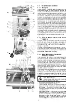
1. Moving  sewing  needle

- risk  of  injury  when  sewing  with  raised  pressure  foot  or  top  roller,  because  the  finger  guard  is  then  positioned  too  high,

- risk  of  injury  when  inadvertently  threading  down  of  the  motor  threadle.

2. Moving  thread  take-up  lever

- risk  of  injury  when  inadvertently  or  intentionally  inserting  the  finger(s)  between  the  thread  take-up  lever  and  its  guard.

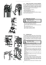
3. Moving  pressure  member

- risk  of  injury  when  holding  sewn  work  in  immediate  vicinity  of  the  pressure  member  and  beginning  to  insert  under  the

pressure  member  a  considerably  thicker  sewn  work  portion,

- risk of injury when sinking the pressure member.

4. When switched off, the clutch motor slows down by inertia but would be reactivated by an accidental treading down of the

motor treadle. To avoid such risk, it is advised to hold the handwheel by hand and slightly to depress the motor treadle.

2. Introduction

This  service  book  contains  instruction  for  regulating  the  mechanisms  of  the  sewing  machine  head.
The instructions for use and for putting the machine into operation and for the control of the stopmotor are not included in this

service  book,  but  they  are  supplied  as  separate  publications.
This  service  book  is  universal  for  all  subclasses  of  the  machine  -  it  contains  setting  procedures  for  all  elements  which  may  be

placed on the machine of the given class. When the supplied subclass of this machine does not include some element, then it is

possible  to  leave  out  the  respective  parts  of  the  instructions.  The  optional  equipments  of  the  machine  and  the  respective

configurations  of  the  subclasses  of  the  machine  are  given  in  the  operating  instructions.
This sewing machine disposes of a large extent of its use. The machine should be set with respect to the parameters of the sewn

material,  the  sewing  thread  etc.  The  setting  for  the  individual  categories  is  given  in  the  chapter  10.2.
For  setting  the  machine,  simple  setting  aids  are  used  which  are  included  in  the  accessory  of  the  machine.  Besides  these  aids,

universal  measuring  devices  are  used,  such  as  slide  calliper,  feeler  gauges  and  dynamometer  for  measuring  the  thread  tension.

All manuals and user guides at all-guides.com

Содержание 4180i-1

Страница 1: ...vice a s Sokolská 60 CZ 680 17 Boskovice Tel 420 516 453434 453433 494111 Fax 420 516 452165 http www minerva boskovice com Edition 10 2005 Printed in Czech Republic S735 000662 All manuals and user guides at all guides com a l l g u i d e s c o m ...

Страница 2: ...echanisms of the main tensioners 3 4 4 Setting the adapting spring 3 4 5 Setting the thread limiter 3 4 6 Setting the additional thread limiter 3 5 Feeding mechanism of the needle feed and of the lower feed wheel 10 3 5 1 Description 3 5 2 Stitch length mechanism 3 5 2 1 Setting the upper eccentric 3 5 2 2 Setting the prop 3 5 2 3 a Forward and rearward stitch length distribution rough 3 5 2 3 b F...

Страница 3: ...tion of the trimming mechanism 4 2 Setting the pickup roller 4 3 Setting the cam 4 4 Setting the fork 4 5 Setting the moving knife 4 6 Setting the height of the fixed knife and of the retaining spring of the lower thread 4 7 Setting the fixed knife 4 8 Setting the retaining spring of the hook thread 4 9 Setting switching of the electromagnets 5 Lifting the top roller by electromagnet 26 5 1 Descri...

Страница 4: ... situations In industrial sewing machines attention should be paid to the following still remaining possible sources of injury 1 Moving sewing needle risk of injury when sewing with raised pressure foot or top roller because the finger guard is then positioned too high risk of injury when inadvertently threading down of the motor threadle 2 Moving thread take up lever risk of injury when inadverte...

Страница 5: ...osen both screws 2 By turning the screws 3 and 4 set the required distance A For setting up use the setting gauge 7 as per the repective figure After having set it tighten carefully the screws By axial shifting of the gear wheel 5 set the axial clearance in such a way that this clearance is the least possible but sufficient for turning easily the hook Tightencarefullythescrews 2 Caution Oneofthese...

Страница 6: ...protective sheet and the hook body 3 we shall reduce the play by levering in applying the pressure on the protective sheet in the sense of the arrow 4 we shall increase the play Check up the protecting effect in pushing against the needle in the sense of the arrow 5 The hook point must not catch the needle If so set up the protecting effect correct eventually the setting of the distanceofthehookpo...

Страница 7: ...nt comes to lie opposite the needle 4 The wheel 2 is to be set with its gear rim symmetrically to the centre of the gear wheel 1 The clearance between the gear wheels is to be the least possible Caution Danger of injury Switch off the main switch Before starting the setting operation wait until the motor stops Set the angle of 2O8 on the handwheel 6 and lock it with the screw 7 On the removed post...

Страница 8: ... bar 11 on the loop 12 is mounted in a ball bearing and it is slidingly mounted on the needle bar carrier The mechanism is lubricated by means of a central wick lubricating system 3 2 2 To check the handwheel angular adjustment The handwheel 5 must be situated in its precise position relative to the needle and thread mechanism This position is given by a pin 2 which locks the connecting rod of the...

Страница 9: ...en the screws 1 and 3 3 2 5 Setting the needle the needle bar holder in the direction of sewing Whenshiftingouttheneedlefromthethroatplateinsert atthemoment when the needle eye is at the level of the top surface of the throat plate insert 3 the distance between the needle and the wall of the throat plate insert must be A 0 2 mm Caution Danger of injury Switch off the main switch Before starting th...

Страница 10: ...ing the setting operation wait until the motor stops Turn slightly the finger 2 in the sense towards the throat plate 1 Place the throat plate 1 and screw in the screws 6 Place the insert 4 and screw in the screws 5 7 3 3 3 Side setting of the throat plate post The post of the throat plate 1 is to be side set in such a way that the axis of the hole in the insert of the throat plate 2 is at the dis...

Страница 11: ...ad from the sewn material when removing the sewn material from the pressing element without leaving the tensioner 3 4 3 Setting the tensioning mechanisms of the main tensioners In the rest position of the tensioners when pushing the plate of the tensionersonthespot A 3 4 1 thisplatemusthavethesocalleddead travelofabout0 5mm Atthislifting thetensiondiscsofthetensioners must not be relieved This can...

Страница 12: ...ring 2 shifts by about 1 4 to 1 2 length of its total length This means that the thicker will be the sewn material and the longer will be the stitch length the more will be the limiter shifted in the sense of the arrow and inversely Under standard sewing conditions the thread limiter is set in its tested positions depending on the sewing category in accordance with the chapter 11 Caution Danger of...

Страница 13: ...ous setting of the eccentric by means of the setting bar Insert the setting bar 3 into the hole in the eccentric 1 and prop it from above against the feeding shaft 4 Shift axially the eccentric 1 on the shaft into its extreme positions and place it in the middle Tighten the screws of the eccentric 1 to the maximum one screw first and after having turned slightly the hand wheel the second screw as ...

Страница 14: ...ng category where the stitch length of the indicator is 3 mm Caution Danger of injury Switch off the main switch Before starting the setting operation wait until the motor stops Screw in the screw of the control knob in such a way that the spherical surface of the screw 3 bears on the seat of the cam 4 Loosen the screw 5 and turn the control knob in the clockwise direction until the pin 6 of the k...

Страница 15: ...ngaging and disengaging with the carrier plate 5 there are in a friction engagement both the cover 1 and also the star 4 namely in the dead centre of the connecting rods 2 and 3 The setting of the change over of clutches is done by tightening or by loosening the nut 13 3 5 3 1 2 Setting the lever of the second step of feeding angle position The lever of the second step 1 must be set in such a way ...

Страница 16: ...isdoneatthemomentwhentheclutchdisks 3 donotmove which means when they are at the dead center of their oscillating movement This corresponds to the angle 90 on the handwheel Caution Danger of injury Switch off the main switch Before starting the setting operation wait until the motor stops Loosenthescrewsoftheindentedpulleyoffeedingandshiftittothe left Set the maximum stitch length Set the angle 90...

Страница 17: ...rrected Caution Dangere of injury Switch off the main switch Before starting the setting operation wait until the motor stops Loosen the screw 3 Loosen the screw 4 Loosen or tighten the screw 5 and push simultaneously with finger the feeder 1 downwards until the required height of the teeth X of the wheel feeder is attained Tighten then still the screw 5 by 45 1 8 revolution Tension the tensioner ...

Страница 18: ...soastoavoidtheslippageofthesewnmaterial when feeding it Method of setting the height of the top roller Lower by hand the presser bar 3 with the top roller 1 above the wheelfeeder 5 Loosen the screw 4 and set the required value A 0 2 mm Tightenthescrew 4 Setting the force of the top roller 1 Inscrewinginthescrew 2 theforceofthetoprollerisincreasedand inversely 3 6 Feeding mechanism of the top rolle...

Страница 19: ...ows Caution Danger of injury Switch off the main switch Before starting the setting operation wait until the motor stops Loosen the screws 1 of the pulley 2 Set the pulley 2 in such a way that the distance of 5 mm is attained in accordance with the illustration Tighten the screws 1 3 6 4 Setting the tensioning roller The tensioning roller of the indented belt of the top feeding is mounted in a rot...

Страница 20: ... a way that it is out of the pulley 4 Remove the pulley 4 Remove the front guard Loosen and unscrew the screw 14 of the holder of the wheel 15 and remove it from the holder 21 Loosen the screws 16 and 17 of the holder 18 Removetheholder 18 togetherwiththeholder 15 andarticulated shaft 13 from the machine Loosen the screws 19 of the pulley 20 Loosen the screw 24 of the ring 25 Hold the pulley 20 an...

Страница 21: ... the required value X and tighten the screw 1 Loosen the screw 5 Byshiftingtheholder 2 intheholder 6 setthebottomedgeofthe roller to the edge of the needle operture Tighten the screw 5 3 6 6 3 Setting the gear clearance and in the mounting of the top roller Intheconegearofthedriveofthetoprollerfoot theminimumclearance must be set A too small clearance will increase the friction resistance of the g...

Страница 22: ...o be A 12 5 mm Caution Danger of injury Switch off the main switch Before starting the setting operation wait until the motor stops Place a cube 1 having the height of A 12 5 0 7 mm under the presserfoot Screw in thoroughly downwards the screw 2 Tighten slightly the screw 3 in such a way that the lever 4 turns on the shaft 5 with a certain friction moment Push with the screwdriver on the lever 4 u...

Страница 23: ...function of the cam on the winders shaft is interrupted and it moves in the sense of the arrow A fine setting is to be done on an incorporated condition in the machine Using the screw 2 thepositionofthefrictionpartofthepickuplever 1 isadapted In opening the lever the stopping function is accelerated Its inverse function delays it A test is to be done after having inserted the bobbin when passing t...

Страница 24: ...lue of the tensioning moment is very sensible to the turning of the nut 5 When setting it it is necessary to proceed very carefully set it up only in emergency cases Check the moment using a torque limiting wrench Caution The clutch guarantees only one mutual position of the hub of the lower shaft 2 and that of the beltwheel 1 Nocheckingaccordingtothegaugemarks isneeded Putting theclutchoutofopera...

Страница 25: ...Before starting the setting operation wait until the motor stops The belt is correctly tensioned when the opposite sides of the belt approach one to another by up to 20 mm in applying the force of 10 N The belt is tensioned in turning respectively the motor in its holder 3 11 2 Replacing the V Belt Caution Danger of injury Switch off the main switch before starting the setting operation wait until...

Страница 26: ...e machine into operation each mechanism of the machine is to be lubricated with several drops of oil Oil is only refilled thereafter into the oil reservoirs using an oil can into the holes in the oil level indicators The oil tanks 1 2 3 of the central distribution is to be filled up to the mark max 3 13 3 Multiple oil use Oil which runs into the oil cup is collected in the collector 1 and may be r...

Страница 27: ...same time t h e shaft 2 up to the stop against the shaft 3 With the holder 1 held on the stop shift the shaft 2 in such a way that there appears the gap A 0 2 to 0 4 mm and tighten the screw 4 Check the gap A in shifting the armature 6 4 3 Setting the cam The position of the cam 1 against the shaft 2 is to be such so that when the adjusting pin is in contact with the shaft 4 the protractor scale o...

Страница 28: ...the height of the fixed knife and of the retaining spring of the lower thread The fixed knife 1 and the retaining spring 2 are fixed on the holder 3 This holder is fixed with the screw 4 on the post of the hook 5 In its height the holder 3 is to be set in such a way so that the top surface of the fixed knife 1 is by 1 8 mm below the top surface of the throat plate Caution Danger of injury Switch o...

Страница 29: ...eter of the moving trimming knife 4 9 Setting the switching of electromagnets The electromagnets of the trimming device and loosening of the tensioner must work in accordance with the diagram This is ensured bysettingthestopmotor seetheinstructionsforuseofthestopmotor 1 1 position of the needle 135 on the handwheel 2 2 position of the needle 64 on the handwheel 3 position of stopping the tensioner...

Страница 30: ...d and in rearward sense If this position is not correct the length of the stitch will be shortened in one or the other feed direction 6 2 Electromagnet height setting Caution Danger of injury Switch off the main switch Before starting the setting operation wait until the motor stops Set the position of the electromagnet 2 in the upper position of the grooves of the guard 3 Proceed to the mounting ...

Страница 31: ...connected Connecting spots 4 backtackingelectromagnet 5 trimmingelectromagnet 6 tensioner loosening electromagnet 7 presser foot lifting electromagnet 8 connector of push button connecting 9 connector of coupling the head with the stopmotor 10 connecting cable of the head and stopmotor Wiring diagram of connecting the electric elements of the machine head 8 Drive control panel position sensor The ...

Страница 32: ...thin the extent from the light to medium heavy duty sewing The setting of the machine must be adapted to the sewing parameters including also replacement of some components such as e g needle the throat plate insert For this reason the setting of the machine is divided into 2 categories 1 light sewing 2 medium sewing In the factory where this machine has been manufactured the machine has been set ...

Страница 33: ...the retaining spring of the trimming device according to the paragraph 4 8 5 There are in use various types of feeders with the purpose of avoiding imprinting the teeth in the lining leather Otherwise it is possible to use any feeder Setting as per chapter Instructions for service 3 5 3 1 2 3 3 2 3 5 3 2 2 3 6 6 1 3 6 6 2 Instructions manual 6 5 6 4 6 4 Instructions for assembling 2 4 4 5 Standard...

Отзывы: