background image

9

ENGLISH 

L2000641  Installation guide for DucoBox Silent  (Revision G | 17.07.2019)

06.E 

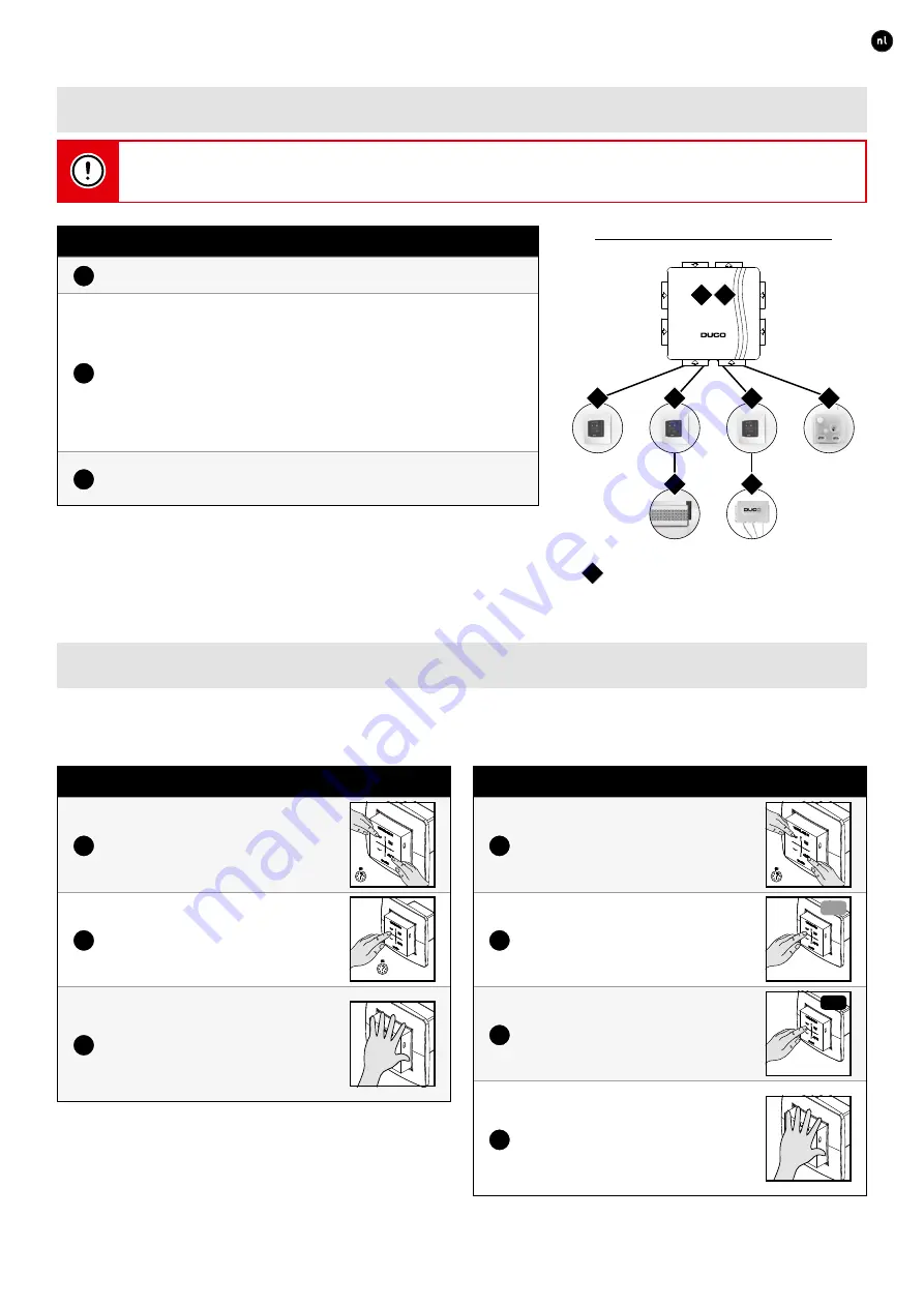
Pairing components

Never pair more than one system with RF components at the same time. If you do so, a component in the wrong 

network could be paired, e.g. in the neighbours’ DucoBox.

Pairing components on the DucoBox Silent Connect

1

Activate ‘Installer mode’ by tapping ‘INST’ on the DucoBox� The LED 

will flash green rapidly�

2

Add control components by tapping once on the component to be 

paired� The LED will flash red briefly and then start to flash green 

rapidly� Repeat this step until all remaining components in the cur-

rent zone have been paired�

With RF components: start with the component closest to the mas-

ter� If the first pairing is unsuccessful, another component may be 

tried first, which can then act as a hop point for components which 

are unable to make an RF connection with the DucoBox�

3

Once all components have been paired, ‘Installer mode’ can be 

deactivated by tapping ‘INST’ on the DucoBox Silent Connect� LEDs 

on all components will stop flashing�

Please refer to the manual with the components for more detailed information�

1

2

3

4

5

6

7

8

Example of a pairing sequence

indicates the order in which a 

button of the component must be 

pressed controls component

X

06.F 

Removing / replacing components

Removing paired components from the network or replacing is only possible within 30 minutes after the component is paired in 

or is restarted� Restarting can be done by disconnecting the power for a moment� After a time-span of 30 minutes, remove and 

replace operations are ignored� This is valid for all components from date of manufacture 

170323

Removing a component

1

Activate ‘Installer mode’ by 

long-pressing 2 diagonal buttons 

on a paired control� The LED will 

flash green rapidly�

5 sec

2

Press once and hold a button on 

the component to be removed 

in order to remove it from the 

network�

5 sec

3

Deactivate ‘Installer mode’ by 

pressing the 4 buttons on a paired 

control simultaneously (or using 

the palm of your hand on a control 

featuring touch buttons)� The LED 

will turn white�

Replacing a component

1

Activate ‘Installer mode’ by 

long-pressing 2 diagonal buttons 

on a paired control� The LED will 

flash green rapidly�

5 sec

2

Press briefly twice on the button 

of the component to be replaced�

2x

OLD

3

Tap once on the button for the new 

component� The latter will take on 

all settings / connections in the 

network�

1x

NEW

3

Deactivate ‘Installer mode’ by 

pressing the 4 buttons on a paired 

control simultaneously (or using 

the palm of your hand on a control 

featuring touch buttons)� The LED 

will turn white�

Содержание DucoBox Silent 225

Страница 1: ...Installation guide ENGLISH DucoBox Silent Connect Product version 17xxxx and above Step by step instructions duco tv L2000641 Revision G 17 07 2019 ...

Страница 2: ...ome 8 06 E Pairing components 9 06 F Removing replacing components 9 06 G Tips 10 07 Air calibration 10 07 A Air calibration procedure for DucoBox Silent Connect 10 07 B Checking 12 08 Maintenance service 12 09 Warranty 12 Vero Duco Handelsstraat 19 8630 Veurne Belgium tel 32 58 33 00 33 fax 32 58 33 00 44 info duco eu www duco eu DUCO HANDELSSTRAAT 19 VEURNE B 8630 09 See www duco eu for informat...

Страница 3: ...itted in every kind of window or installation site to louvres with sound absorbing qualities for projects where there is exposure to mild levels of noise fire resistant louvres custom louvres for high rise buildings to ventilation and solar shading in a single product or electronically controlled louvres with preheating See www duco eu for more info Pre dis assembly instructions see www duco eu An...

Страница 4: ...tdicht vast via tape slangklem of tiewrap Gebruik geen schroeven bij bevestiging Kies een dakdoorvoer met lage weerstand Houd de DucoBox luchtdicht Sluit het deksel goed en plaats een dop op elke niet gebruikte aansluitmond installatietips kanalen DucoBox Silent Focus nl 7 8 9 10 3 4 5 6 1 2 De goede werking van uw Duco ventilatiesysteem is volledig afhankelijk van de keuze en uitvoeringskwaliteit...

Страница 5: ...uni cation Print see page 7 RF RF Wired RF 24 VDC 24 VDC 24 VDC 230 VAC 230 VAC A A B B GND GND B A GND POWER SUPPLY User controller User controller Max 99 Wired 25 RF Tronic vent Tronic vent 230 VAC 230 VAC DucoBox Silent Connect RF obstacle free zone Do not place any obstacles causing RF interference or other devices with an RF connection within a radius of at least 30 cm around the RF component...

Страница 6: ...ed The cable required is a 5 x 0 75 mm data cable We strongly advise using a shiel ded cable This is to prevent any interference that may affect the data communi cation Any Tronic grilles will be supplied with a 5 x 0 25 mm cable which can be connected via a splicing terminal block DUCO WIRED Power supply 24 VDC Wiring 5 x 0 75 mm 5 x 0 25 mm from Tronic grilles Maximum distance up to 300 m Maximu...

Страница 7: ... can be done using the Duco Network Tool This user friendly software also enables problems in the system to be pinpointed The Duco Network Tool is issued to every installer af ter attending a free training course at the Duco Academy Please refer to our website or your Duco dealer for further information Only in Belgium and the Netherlands 06 B Installer User mode To add components to the network r...

Страница 8: ...tting type of home Setting the type of home and number of occupants correctly will provide the ventilation system with a better basis to adjust the mid position There are two types of home low rise e g a house and high rise e g a flat Configuration of this component is obligatory in the Netherlands The standard setting for a DucoBox is as a low rise home for 4 or more occupants Setting type of hom...

Страница 9: ...h a button of the component must be pressed controls component X 06 F Removing replacing components Removing paired components from the network or replacing is only possible within 30 minutes after the component is paired in or is restarted Restarting can be done by disconnecting the power for a moment After a time span of 30 minutes remove and replace operations are ignored This is valid for all ...

Страница 10: ...r information about determining ventilation flow rates 07 A Air calibration procedure for DucoBox Silent Connect The air calibration procedure must be carried out on a calm day no more than wind force 2 leaves rustling fee ling the wind in one s face Air calibrating the DucoBox Silent Connect 1 Set all exhaust vents so they match the desired flow rate in accor dance with the table below Proper pre...

Страница 11: ...rate is obtained This can be done in two ways Using the lower and higher buttons on a paired User controller or CO2 Humidity Sensor Using the DOWN and UP buttons on the DucoBox This requires the cover to be removed temporarily Always close the cover after every measurement Pressing the buttons once is equal to 1 approximately 2 to 3 m h per press of the button depending on the restriction in the d...

Страница 12: ...after 15 minutes 08 Maintenance service Please refer to the maintenance instructions at www duco eu and view the videos on duco tv for more information For service problems as a user Please contact your installer Keep the serial number of your product to hand For service problems as an installer Please contact your Duco products seller Keep the serial number of your product to hand 09 Warranty All...

Страница 13: ...13 ENGLISH L2000641 Installation guide for DucoBox Silent Revision G 17 07 2019 ...

Страница 14: ...14 ENGLISH L2000641 Installation guide for DucoBox Silent Revision G 17 07 2019 ...

Страница 15: ...15 ENGLISH L2000641 Installation guide for DucoBox Silent Revision G 17 07 2019 ...

Страница 16: ...16 ENGLISH L2000641 Installation guide for DucoBox Silent Revision G 17 07 2019 Installed by L2000641 Document last modified on 17 07 2019 revision G ...

Отзывы: