


Installation, operation and maintenance instructions - DualSun XXXM
–
60
–
3BBP
V1.2
–
March 2020
Page
20
sur
41
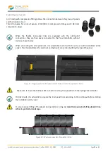
b.
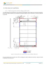
Checking the roof layout
The positioning of the first module depends on the corrugation crest routing detailed above. Then check that each
DualSun fitting is correctly positioned in the corrugation recess, according to the width of the inter-panel clamps,
respecting the minimum distances for the routing of the hydraulic links through the corrugation crests.
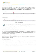
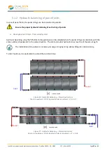
Portrait layout
Figure 16 : Portrait layout
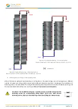
Landscape layout
Figure 17 : Landscape layout
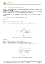
Sheet metal roof with 333 mm corrugation length : Select an inter-panel distance of 16.67 mm if possible
and place the end of the module 325 mm from the centre of the corrugation crest. The position of the
modules will thus be identical in relation to the corrugation crests over the entire layout.
c.
Checking the routing of the hydraulic links
Routing perpendicular to the corrugations
–
Configurations 3.2.3.1 and 3.2.3.3
The previous points allow to check the routing of the hoses perpendicular to the corrugations according to the
characteristics of the DN15 or DN26 hoses, to the height of elevation of the modules and to the positioning of the
hydraulic links in relation to the corrugations.
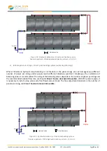
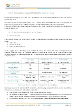
Routing parallel to the corrugations
–
Configurations 3.2.3.2 and 3.2.3.4
Routing through rails may occur according to the mounting system. In this case it is possible to run the hydraulic links
beneath or from the side of the rails.
It is necessary to ensure that :
-
The height between the rails and the roof surface is greater than the external diameter of the flexible hoses,
see table 1 above.
-
The bending radius of the flexible hose is greater than the minimum bending radius to avoid the rails, see
table 1 above.
-
The rails are at a sufficient distance from the hydraulic fittings to comply with the minimum bending radii of
the flexible hoses within the permissible fixing areas, see 3.2.1.


