background image

fpv

RAcing

Equipment Required

(Aircraft / Multicopter system)

Transmitter - 

6 Channel or above

Receiver - 6 Channel or above, PPM,DSM,SBUS signal

FPV Goggle

Balance Charger 

3 cells or 4 cells Li-po Battery

Flight Steps

1. Install Receiver (self-provided) (Please refer to P.2 - Intall Compatible RC Receiver) to quad
2. Install Battery (self-provided) (Please refer to P.1 - Battery Installation)
3. After binding (self-provided) Receiver and Transmitter (self-provided), please go to the 
    pre-flight check (Please refer to P.9 - Pre-flight check)
4. Install Props (Please refer to P.19 - Main Blade Assembly Introduction)
5. Motor Unlock (Please refer to P.13 - Motor Unlock)

Motor Unlock

After Binding, Place the throttle stick at the bottom and push the aileron stick to the rightmost for at least 
3 second . Then release.

Mode 1

Mode 2

Aileron Stick Throttle Stick

Throttle/Aileron Stick

13

Содержание Q220

Страница 1: ...快速操作手冊 Quick Guide User Manual ...

Страница 2: ...fety Note Racing Instruction Remove Props Li po Low V Alarm Safety Note General Packing Contents Details Packing Contents Equipment Required Flight Steps Motor Unlock Main Control Board Introduction Flight Control Introduction Welding Introduction Assembly Introduction Main Blade Assembly Introduction Control Mode AUX1 Flight Mode Switch AUX2 OSD and Beeper Switch Compatible Open Source Spare Part...

Страница 3: ...safe areas away from other people Do not operate R C aircraft indoors or within the vicinity of homes or crowds of people R C aircraft are prone to accidents failures and crashes due to a variety of reasons including lack of maintenance pilot error and radio interference Pilots are responsible for their actions and damage or injury occurring during the operation or as of a result of R C aircraft m...

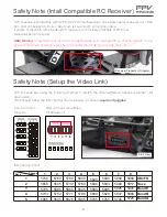
Страница 4: ...rd Pilot should follow the ISM channel chart as below to connect quad and goggles DSM Binding Plug DSM receiver into correspondence port and switch all channel switch to top power on the main control board Then it will enter the binding mode with alert Bi ISM channel chart 5733 5658 5740 5705 5865 5752 5695 5760 5685 5845 5771 5732 5780 5665 5825 5790 5769 5800 5645 5805 5809 5806 5820 5885 5785 5...

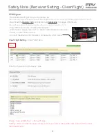
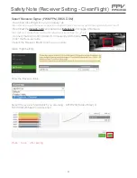
Страница 5: ... en US Download the Version 1 2 4 and install it as Extensions in Goggle Chrome as https github com cleanflight cleanflight configurator releases tag CLFL_v1 2 4 Connect the Main Control Board to computer by USB Cable Enter the Receiver table Select the Receiver Brand which you are using Clean Flight Setting Press Save after setting Select the receiver brand which you are using AETR1234 Futaba Hit...

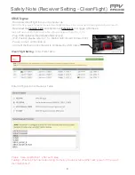
Страница 6: ...m cleanflight cleanflight configurator releases tag CLFL_v1 2 4 Plug PWM receiver into correspondence port Port Position please refer to P 14 Main Control Board Introduction Power on the Main Control Board Connect the Main Control Board to computer by USB Cable Clean Flight Setting Enter Ports Table Press Save and Reboot after each step Testing Ensure 6 channel is operating normally at receiver ta...

Страница 7: ...com cleanflight cleanflight configurator releases tag CLFL_v1 2 4 Plug PPM receiver into correspondence port Port Position please refer to P 14 Main Control Board Introduction Power on main control board Connect the Main Control Board to computer by USB Cable USB Socket Placement Clean Flight Setting Enter Ports Table Press Save and Reboot after each step Testing Ensure 6 channel is operating norm...

Страница 8: ...com cleanflight cleanflight configurator releases tag CLFL_v1 2 4 Plug PWM receiver into correspondence port Port Position please refer to P 14 Main Control Board Introduction Power on main control board Connect the Main Control Board to computer by USB Cable USB Socket Placement Clean Flight Setting Enter Ports Table Press Save and Reboot after each step Testing Ensure 6 channel is operating norm...

Страница 9: ...pondence port Port Position please refer to P 14 Main Control Board Introduction Switch all channel switch to bottom Power on the main control board Then it will enter the binding mode with alert Bi Binding Transmitter and Receiver Power off the main control board then switch all channel switch to top Power on the main control board connect the mainboard to computer by USB Press Save and Reboot af...

Страница 10: ...etting Adjust the transmitter parameter Travel let Roll Pitch Yaw Throttle Lowest value within 1000 1096 and the largest value within 1944 1999 in the Receiver Table AUX 1 and 2 are on your transmitter and there will be have 3 switches Default mid point DSM PPM 1500 SBUS PWM 1520 ...

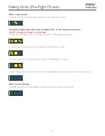
Страница 11: ... Green Chcek the transmitter stick and condition LED is it at the same direction MUST process in Motor Lock Mode Push Elevator Stick to Top Left Right Condition LED flashing in Yellow Push Aileron Stick to Left Left Condition LED flashing in Yellow Push Aileron Stick to Right Right Condition LED flashing in Yellow Push Throttle Stick to Top in Motor Lock Mode Middle Condition LED solid in Blue and...

Страница 12: ...del unplug the battery before walking back to pilot area This ensures that collisions at race start don t affect other pilots A distance of at least 10 meters is recommended more than this is a bonus Warn pilots and be ready to power down IMMEDIATELY if a pilot is affected and wait until he lands Remember that it only takes a seond or two when flying race quads at speed to crash and damage the qua...

Страница 13: ...such as carbon fiber and polyethylene Plastics are very susceptible to damage or deformation from extreme heat and cold climate 警 告 WARNING Frequency interference can cause your model or other models to crash Then guidance provided by an experienced pilot will be invaluable for the assembly tuning trimming and actual first flight or unforeseen danger may happen 警 告 WARNING Operate this unit within...

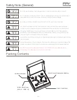
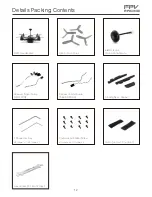
Страница 14: ...M2x5mm x 6 Round Head Socket Screw M2 5x6mm x 1 M2 5x6mm x 1 L Shape Hex Key Landing Skid Rubber Velcro Hard x 1 Rough x 1 Q220 Main Props Hex Handle For Main Props Receiver Signal Cable SBUS DSM2 X 5 8G Circular Polarization Antenna Receiver Signal Cable PWM PPM 12 ...

Страница 15: ...f provided Please refer to P 1 Battery Installation 3 After binding self provided Receiver and Transmitter self provided please go to the pre flight check Please refer to P 9 Pre flight check 4 Install Props Please refer to P 19 Main Blade Assembly Introduction 5 Motor Unlock Please refer to P 13 Motor Unlock Motor Unlock After Binding Place the throttle stick at the bottom and push the aileron st...

Страница 16: ...ket 17 SBUS Signal Input Socket 18 PWN Signal Input Socket 19 Flight Control Socket 20 Channel Switcher 21 External Buzzer Conditional LED Socket 22 PPM Signal Input Socket 23 B ESC Control Signal Socket S1 24 Red LED Light Socket Rear 25 B ECS Power Connecter S1 26 Flight Control Buzzer 27 Li Po Battery Socket 28 B ECS Power Connecter S3 29 B ESC Control Signal Socket S3 30 Red LED Light Socket R...

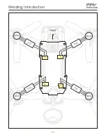
Страница 17: ...fpv RAcing Welding Introduction ESC ESC ESC S1 S3 S4 S2 FRONT ESC Motor Motor Motor Motor 15 ...

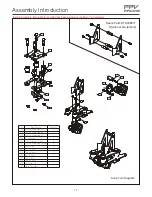
Страница 18: ...Quantity 001 005 Left Body Cover Plastic 008 Right Body Cover Plastic 007 LED Light Set Green 006 Arm Cover Rear 009 Mount Rod for Center 010 LED Light Set Red 012 Main Control Board 011 LED Light Set F C Condition 013 Main Plate Bottom 014 M2 6 Screw 015 M2 5 6 Screw 016 Top Fixed Plate Front 023 M2 5 Screw 4 2 1 2 2 1 2 8 2 1 1 1 8 1 2 1 Assembly Introduction Before Assembly Ensure Motor and ESC...

Страница 19: ...tity 017 021 Top Fixed Plate Front 024 M2 12 Screw 023 M2 5 Screw 022 Camera Damping Ball Ring 025 Camera Mount 026 M2 16 Screw 028 Camera Mount 027 FPV Camera 029 M2 Screw Nut 030 Video Tx Holder 4 1 2 4 4 1 1 1 1 1 1 1 1 Assembly Introduction Before Assembly Ensure Motor and ESC has been welding on the Main Control Board Spare Parts DTS006871 Optional Equipment Step Two Diagram 17 ...

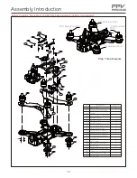
Страница 20: ...am 047 Flight Control Holder Bottom 1 M2 5 Screw 023 No 031 Battery Fixed Plate Side 032 O Ring Specification Quantity 033 Cover for Receiver Placement 036 M2 5 8 Screw 035 M2 5 12 Screw 034 Antenna Mount 037 Battery Fixed Plate Center 038 CW Brushless Motor 040 Front Arm Cover Plastic 039 CCW Brushless Motor 041 Rear Arm Cover Plastic 042 Motor Mount 043 M2 7 Screw 044 5 8GHz Antenna Mount 046 Fl...

Страница 21: ...2 2 1 1 1 059 058 059 044 048 050 049 023 051 057 052 053 054 056 055 Main Blade Rotation Direction Bullet Head Nut Tightening Direction Main Blade Rotation Direction Bullet Head Nut Tightening Direction Bullet Head Nut Tightening Direction Main Blade Rotation Direction Main Blade Rotation Direction Bullet Head Nut Tightening Direction Main Blade Rotation Direction Bullet Head Nut Tightening Direc...

Страница 22: ...if the left stick push to the top and it wasn t bounce back to middle it should be Mode 2 Mode 1 we can find it in Euro usually To identify Mode 1 we can find where is the throttle stick if the right stick push to the top and it wasn t bounce back to middle it should be Mode 1 Otherwise Mode 3 and Mode 4 is a very special control mode we won t use these mode if you are beginner either you very und...

Страница 23: ...e is the ideal mode to have fun with flips and rolls fpv RAcing AUX1 Flight Mode Switch Three flight modes are configured by the Clear Flight and are maped by default to channel 5 AUX1 of the R C Tx These modes are as follows Horiz Pos 2 Horiz mode is a bit of a hybrid mode It does auto level buy also allows flips and rolls Angle Pos 1 Angle mode is the easiest to learn When the sticks are centere...

Страница 24: ...ate knowledge of the flight controller API care must be taken when installing updated Cleanflight builds DTS team may not have support for Beta and recently released Cleanflight builds the day they are released buy we are committed to keep up with changes Check the DTS product page for compatibility information Clean Flight Configurator Connection To hook up the Clieanflight Configurator hook up a...

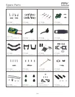
Страница 25: ...ront Rear DTS006890 Top Fixed Plate Front DTS006891 Damping Ball Set 4PCS DTS006892 Top Fixed Plate Center Rear DTS006893 Mount Rod Long for Front Rear DTS006855 Mount Rod Short for Center DTS006856 LED Light Set F C Condition GWY006858 Camera Mount Set DTS006859 Antenna Mount Set DTS006861 Bullet Head Nut CW CCW DTS006866 for Action Camera DTS006871 Landing Skid Plastic DTS006933 Camera fixed Mou...

Страница 26: ...WY006878 Motor cover Black DTS007056 Main Blade Set Black DTS006886 Motor Cover Orange DTS007057 ESC 30A GWY006899 GWY006900 Antenna Set RHCP LHCP 24 Main Control Board GWY007087 With 30A 25mW PAL Main Control Board GWY007084 With 20A 25mW NTSC Main Control Board GWY007088 With 30A 25mW NTSC Main Control Board GWY007085 With 20A 200mW NTSC Main Control Board GWY007089 With 30A 200mW NTSC Main Cont...

Страница 27: ...er Mode 2 GWY006227 AH6T Transmitter Mode 1 GWY007092 25 GWY006952 Short Lens NTSC GWY006954 Long Lens PAL GWY006955 Short Lens PAL GWY00xxxx 720P 60F Storage Camera GWY007083 DSM Signal Output Receiver GWY007082 SBUS Signal Output Receiver GWY006939 Aluminium Box ...

Страница 28: ...Stator Arms 12 Max Continuous Current 3mins 18A Max continuous Power 3mins 198W Magnet Poles 14 Dimesion 5 x 27 7 x 30 7cm Weight 28 4g 5 8G Video Transmitter Input Voltage 5V Operating Current 350mA Operating Frequency 5 8GHz Antenna Interface SMA Transmitting Power 25mW 200mW 600mW Selectable Dimesion 30 x 21mm Weight 3g Circular Polarized Antenna Transmitter Operating Frequency 5 8GHz Antenna G...

Страница 29: ...fpv RAcing ...
Отзывы: