User Manual
DSPECIALISTS
Digitale Audio- und Messsysteme GmbH
Helmholtzstr. 2-9 L D-10587 Berlin
http://www.dspecialists.de
Страница 1: ...User Manual DSPECIALISTS Digitale Audio und Messsysteme GmbH Helmholtzstr 2 9 L D 10587 Berlin http www dspecialists de ...
Страница 2: ...6 1 9 Selecting the monitoring channel 10 6 1 10 Setting the audio cycle and the synchronization source 11 6 1 11 Loading and saving settings 11 6 1 12 Manually updating the X 8 software 12 6 1 13 Automatic recognition of outdated firmware 12 6 1 14 Advanced settings 13 6 1 15 Device information 14 6 1 16 GUI information 14 6 2 Settings on the X 8 15 6 2 1 Configuration of the input and output amp...
Страница 3: ...ine Outs 21 9 2 4 Mic Line In 1 to 4 22 9 2 5 Line In 1 to 8 24 9 2 6 S PDIF input and output 25 9 2 7 Headphone socket 26 9 3 ASIO and X 8 channel assignment 26 9 4 Connection logic and status change 27 9 5 Configurations in X 8 GUI vs X 8 device 27 9 6 Block diagram of X 8 28 10 Contact Imprint 29 ...
Страница 4: ...User Manual AUBION X 8 This page is intentionally left blank ...
Страница 5: ...metres with standard CAT5e cables for your measurement device measurement PC and network The integrated Zeroconf technology configures the IP network settings automatically In connection with the X 8 drivers which are included in the package you can concentrate immediately on your measurement work without having to be a network expert a real plug and play system The included AUBION X 8 Multiclient...
Страница 6: ...rt 5353 2 The X 8 device driver and control software X 8 GUI can be found on the CD provided Start the setup exe file on the CD and follow the instructions that appear on your screen After the software has been successfully installed the X 8 GUI Aubion X8 exe can be found in the AUBION X 8 bin folder in Program Files Start the software by clicking the desktop symbol or go to the Windows start menu...
Страница 7: ...nd four audio channels to the X 8 and are also used for configuration and firmware updates via an Ethernet network Input channels 1 to 8 o 4 symmetric Mic Line inputs to 4 XLR TRS combo sockets in 1 to 4 o 4 Line inputs IN 1 to 4 as well as 4 more symmetrical Line inputs to D SUB25 socket IN 1 to 8 o Alternatively to Line In 7 8 you have the option of S PDIF In 7 8 S PDIF In can be connected to an...
Страница 8: ...chronization o Synchronization either on internal master 44 1 kHz 48 kHz 88 2 kHz and 96 kHz can be set in the X 8 GUI or on the S PDIF IN master clock1 o The synchronization status is shown by an LED on the rear side EXT SYNC off internal on S PDIF In Mains connection 17 to 27 VDC for the mains adapter provided max 20W The technical data for the X 8 can be found in section 9 1 An enlarged block d...
Страница 9: ...guration switches A menu with additional functions A status display along the bottom shows information on the GUI version and the X 8 service as well as on the hardware and firmware of any device connected On the left hand side there is a drop down list in which the X 8 devices available in the network are shown As soon as the X 8 GUI or the X 8 service working in the background is connected to an...
Страница 10: ...nput and output gains source selection etc and the signal level in real time In addition further X 8 GUI devices and GUI information are shown at the bottom 6 1 15 and 6 1 16 If the X 8 is already connected at the moment of selection to another PC or X 8 service the connection will not take place immediately a selection window Device is busy will appear informing you about what PC IP address the X...
Страница 11: ... with a sine signal that is emitted from the Line outputs Out 1 and Out 2 the unloaded electrical level measured differentially at the TRS connections is 3 dBu 6 dBu 12 dBu or 21 dBu depending on the setting The Line Out full scale level can be reached in the X 8 GUI in the File menu using the sub item Device Settings F9 In the AUBION X 8 window that opens select the Device tab which takes you to ...
Страница 12: ...ack from Line to Mic You can only choose the input type for the first four input channels using the X 8 GUI 6 1 5 Mic settings The Mic settings for the corresponding input channel can only be carried out if the input has been configured as a Mic channel see section 6 1 4 You will find the respective input amplification and the de activation of the phantom power supply in the Mic settings The four ...
Страница 13: ...In channels for the corresponding input channel can only be carried out if the input has been configured as a Line channel see section 6 1 4 Line inputs 5 6 can be set at all times while it is only possible to set the Line inputs 7 8 when SPDIF in 7 8 is not activated All eight Line inputs In 1 to 8 have one fader each which you can use to set a level from among four different input amplification ...
Страница 14: ...2 In 1 to In 8 These signal sources are output equally on two headphone channels The monitoring channel is supplied from the channel that was configured last either by sliding the respective fader by clicking the In Out switches below the fader by using the Mic Line switchover or by changing the phantom power supply setting The monitoring channel source signal for the two Line Out channels is loca...
Страница 15: ... selected here The X 8 configured in each case is the clock master This setting also influences the treatment of the sampling rate of the two S PDIF In channels IN 7 8 see section 6 1 8 Future firmware versions will also have an additional option Slave S PDIF In clock master Please notice Some ASIO applications do not automatically detect a change of the sample rate Before changing the device s sa...
Страница 16: ...mware version e g r876 If it is the version you want activate the update process by clicking Install New Firmware The progress bar now shows you the update status If your update has been successful the X 8 device will restart and reconnect with the GUI automatically 6 1 13 Automatic recognition of outdated firmware As soon as the X 8 GUI connects to an X 8 device it compares the firmware status of...
Страница 17: ...in window If this message occurs during a measurement the measurement must be repeated If a connection error occurs repeatedly you can find out the specific error parameters using Show Statistics Hide Statistics closes the window again So that you do not have to write down all values of the connection parameters you can create a log file using Logging activated The log file dev_log_AubionX8_ log i...
Страница 18: ...on displayed comprises the following AubionX8_00 00 3b unique identification of the X 8 10 0 10 201 automatically allocated IP address of the X 8 v2 hardware version of the X 8 r553 boot loader version on the X 8 r876 firmware version on the X 8 48000 Hz currently set sampling rate of the X 8 6 1 16 GUI information In addition the GUI shows the version information of the GUI itself and of the unde...
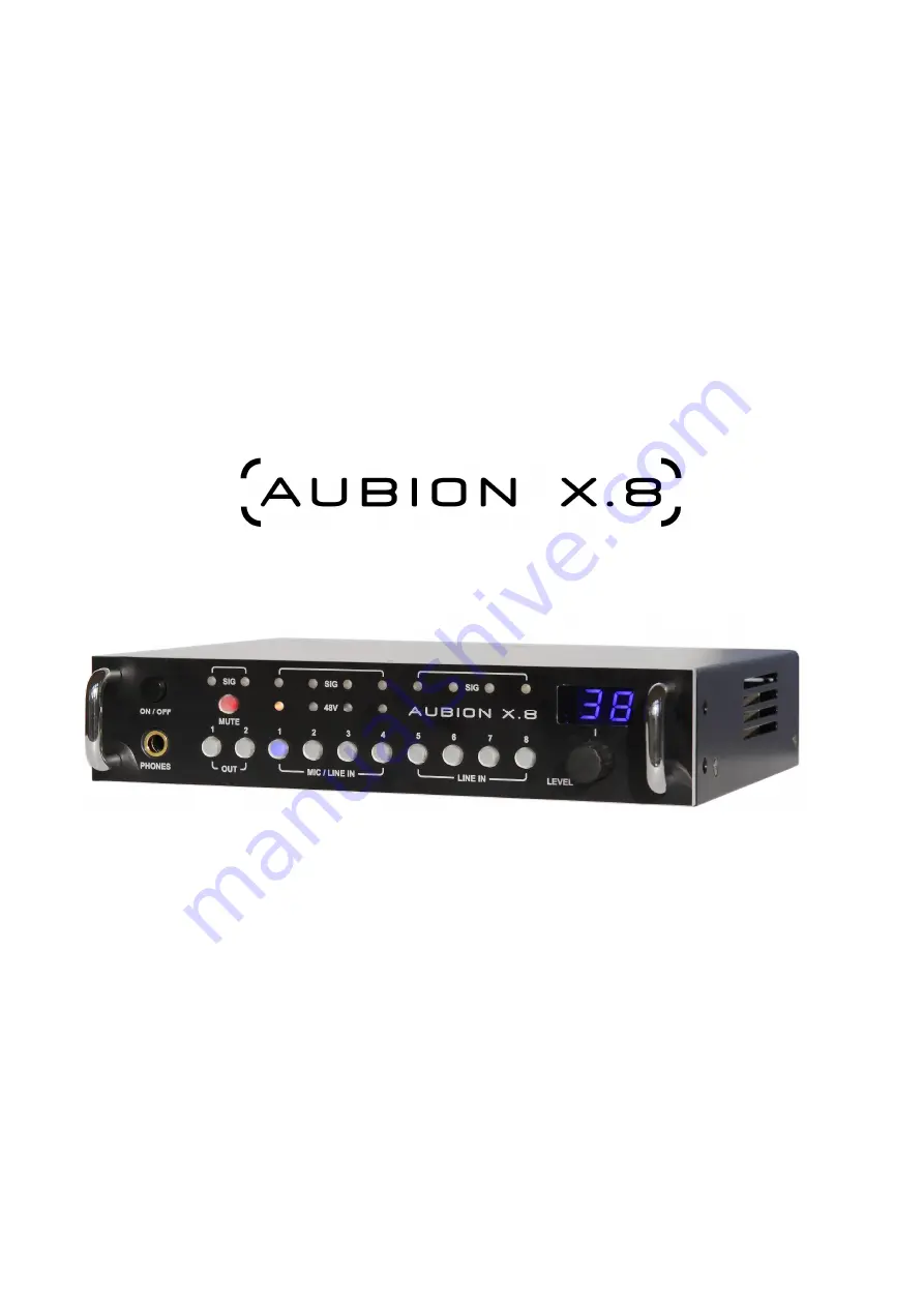
Страница 19: ... LINE IN 5 8 The respective button of each channel lights up blue to confirm At the same time the two digit number display shows the amplification factor set for this channel By turning the control knob LEVEL the input and or output amplification is adjusted immediately The settings are always saved in the device The Line Out amplifications in the range 0 to 99 are displayed with negative prefixes...
Страница 20: ...Speak means digital full scale for a sine signal 6 2 3 Line Out mute There is a MUTE button above the two Line Out channel selector switches which lights up red when the Mute status is active If this button is pressed the two Line Out signals are switched off 6 2 4 Status of the phantom power supply Four lamps with 48V on them are located above the four input channel selector buttons IN 1 4 which ...
Страница 21: ... channel as this can lead to artifacts 8 Working in SysTune and EASERA SysTune and EASERA are used in the same way as other sound cards with an ASIO driver The ASIO driver comes under the name of AUBION X 8 and is simple to select In SysTune the driver is selected using the Select Device command in the Configure menu From version 1 2 onwards SysTune also supports calibration of the set gains this ...
Страница 22: ...nternal 44 1 kHz 48 kHz 88 2 kHz and 96 kHz 176 2 kHz 192 kHz optional Clock synchronization Internal master external via S PDIF In S PDIF input data sample frequency 28 kHz 200 kHz Frequency response AD DA 0 1 dB 20 Hz 20 kHz fs 48 kHz Power Supply DC Plug 24 V DC 20 W max supplied by external mains power supply EU US and UK jacks available Device control and display Gain control and display for ...
Страница 23: ...16 plug fitting to sockets in all continental European countries and several areas in the Middle East Africa South America Asia and Russia and former Soviet republics US NEMA 1 15 plug for sockets in the United States and a further 38 countries outside North America UK BS 1363 plug for sockets in Great Britain Technical data of power input socket Input voltage Power Socket 24 V DC 20 W 5 5 mm 2 5 ...
Страница 24: ...ver Gigabit Ethernet transceivers fully compliant with the applicable sections of IEEE802 3 and IEEE802 3ab Speed Each port works at 10 Mbps 100 Mbps or 1000 Mbps in full duplex mode Rx Tx mapping Auto MDI X integrated thus no requirement if cross link or straight cables used Mates with Standard CAT5e with RJ45 connectors LED 1 on Gigabit link LED 2 on link flickering data activity 8 1 2 3 4 5 6 7...
Страница 25: ...dBu 12 dBu 6 dBu 3 dBu dependent on analog gain i e full scale level refer to section 6 1 3 Frequency response fs 48 kHz 20 Hz 20 kHz 0 1 dB THD N 0 001 21 dBu over full bandwidth 0 0003 21 dBu and f 10 kHz Output Impedance 200 Ohm Mates with TRS jacks Tip Non inverted signal hot Ring Inverted signal cold Sleeve Shield Please be careful not to connect a phantom powered Mic Input with one of the Li...
Страница 26: ...d Max level 0 dBFSpeak 9 dBu 1 dBu 2 dBu 56 dBu dependent on mic in gain refer to section 6 1 5 Frequency response fs 48 kHz 20 Hz 20 kHz 0 2 dB THD N full bandwidth 0 003 9 dBu 0 03 56dBu i e 65 dB gain 0 0003 9 dBu and f 10 kHz Input Impedance 5 2 kOhm Phantom power 48 V 1V source impedance 6 8 kOhm per rail Mates with XLR male plugs 1 Shield 2 Non inverted signal hot 3 Inverted signal cold Plea...
Страница 27: ...In gain refer to section 6 1 7 Frequency Response fs 48 kHz 20 Hz 20 kHz 0 2 dB THD N full bandwidth 0 003 21 dBu 0 001 12 dBu and 6 dBu 0 002 3 dBu Input Impedance Dependent on Max Level or gain resp 1 9 kOhm 21 dBu 2 5 kOhm 12 dBu 5 0 kOhm 6 dBu 15 0 kOhm 3 dBu Mates with TRS male plugs Tip Non inverted signal hot Ring Inverted signal cold Sleeve Shield T Non inverted R Inverted S Shield Non inv...
Страница 28: ... THD N full bandwidth 0 003 21 dBu 0 001 12 dBu and 6 dBu 0 002 3 dBu 0 0003 21 dBu and f 10 kHz Input Impedance Dependent on Max Level or gain resp 1 9 kOhm 21 dBu 2 5 kOhm 12 dBu 5 0 kOhm 6 dBu 15 0 kOhm 3 dBu Mates with AES59 TASCAM D type male connector Different from AES59 Channel order reversed for device serial numbers SN 11 1029 1 2 3 4 5 6 7 8 9 10 11 12 13 14 15 16 17 18 19 20 21 22 23 2...
Страница 29: ...e S PIDF output RCA socket Standards conformance AES3 S PDIF IEC 60958 EIAJ CP 1201 Electrical interface 75 Ohm unbalanced AC transformer coupled Input sample rates 28 kHz 200 kHz Aubion clock master i e sample rate conversion active 44 1 kHz 48 kHz 88 2 kHz and 96 kHz Aubion clock slave Output sample rates 44 1 kHz 48 kHz 88 2 kHz and 96 kHz related to internal sample rate Mates with RCA male plu...
Страница 30: ... bandwidth Output Impedance 20 Ohm Mates with TRS jacks Tip Left Ring Right Sleeve Shield GND Left Right GND Left Right 9 3 ASIO and X 8 channel assignment The following table documents the assignment of the physical X 8 audio channels to the ASIO channels ASIO Playback Channel 1 2 3 4 AUBION X 8 Channel Line Out 1 Line Out 2 S PDIF Out L S PDIF Out R ASIO Record Channel 1 2 3 4 5 6 7 8 AUBION X 8...
Страница 31: ...hannel 50 dBFSrms LED off 3 dBFSrms LED red other LED green Gain settings Line Out reference level Mic Line In and Line Out gains Mic Line In and Line Out gains Mic Line In switchover Per channel 1 to 4 no configuration Phantom supply Per channel 1 to 4 no configuration Mute Line Out One button for Mute On Off of the Line Out channels 1 2 One button for Mute On Off of the Line Out channels 1 2 Sta...
Страница 32: ...User Manual AUBION X 8 28 29 9 6 Block diagram of X 8 ...
Страница 33: ...s a whole Technical data and equipment may be subject to change without prior notice Trademarks All trademarks are the property of their respective owners Windows Windows XP Windows Vista and Windows 7 are trademarks of Microsoft Corporation ASIO is a trademark of Steinberg Media Technologies GmbH TASCAM is a trademark of TEAC Corporation EASERA and SysTune are trademarks of AFMG Technologies GmbH...