


DSE7110 & DSE7120 Operator Manual
32
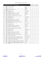
7.4
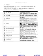
WARNINGS
Warnings are non-critical alarm conditions and do not affect the operation of the generator system, they serve to draw the
operators attention to an undesirable condition.
In the event of an alarm the LCD will jump to the alarms page, and scroll through all active warnings and shutdowns.
Warning alarms are self-resetting when the fault condition is removed.
Display
Reason
Battery High Voltage
The DC supply has risen above the high volts setting level for the
duration of the high battery volts timer
Battery Low Voltage
The DC supply has fallen below the low volts setting level for the
duration of the low battery volts timer
CAN ECU Warning
The engine ECU has detected a warning alarm and has informed
the DSE module of this situation. The exact error is also indicated
on the module’s display.
Charge Alternator Failure
The auxiliary charge alternator voltage is low as measured from
the W/L terminal.
Digital Input A-D
Auxiliary Digital inputs can be user configured as Digital inputs
and will display the relevant icon.
Analogue Input A-C
Auxiliary Analogue inputs can be user configured as Digital inputs
and will display the relevant icon.
Fail To stop
The module has detected a condition that indicates that the
engine is running when it has been instructed to stop.
NOTE:
NOTE:
NOTE:
NOTE:---- ‘Fail to Stop’ could indicate a faulty oil pressure
‘Fail to Stop’ could indicate a faulty oil pressure
‘Fail to Stop’ could indicate a faulty oil pressure
‘Fail to Stop’ could indicate a faulty oil pressure
sensor
sensor
sensor
sensor ---- If engine is at rest check oil sensor wiring and
If engine is at rest check oil sensor wiring and
If engine is at rest check oil sensor wiring and
If engine is at rest check oil sensor wiring and
configuration.
configuration.
configuration.
configuration.
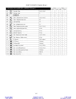
Generator High Voltage Warning
The generator output voltage has risen above the pre-set pre-
alarm setting.
Generator Low Voltage Warning
The generator output voltage has fallen below the pre-set pre-
alarm setting after the Safety On timer has expired.
High Coolant Temperature Warning
The module detects that the engine coolant temperature has
exceeded the high engine temperature pre-alarm setting level
after the Safety On timer has expired.
Low Oil Pressure Warning
The module detects that the engine oil pressure has fallen below
the low oil pressure pre-alarm setting level after the Safety On
timer has expired.
Low Fuel Level
The module detects that the fuel level is below the configured
setting
Over Frequency Warning
The generator output frequency has risen above the pre-set pre-
alarm setting.
Over Speed Warning
The engine speed has risen above the overspeed pre alarm
setting
Under Frequency Warning
The generator output frequency has fallen below the pre-set pre-
alarm setting after the Safety On timer has expired.
Under Speed Warning
The engine speed has fallen below the underspeed pre alarm
setting
Flexible Sensor
The flexible sensor warning alarm has been triggered.
CALL US TODAY
1-888-POWER-58
REQUEST A QUOTE
SHOP ONLINE
www.genpowerusa.com