background image


F-160

N.O.

CONTROL

BOARD

L-250

N.C.

L-250

RESET

N.C.

FRAME GROUND

L1(LINE NO CONNECTED)

L2(LINE COMMON)

L1(LINE HOT)

THERMOSTAT

TERMINALS

N.O.

HOPPER LID

SWITCH

N.O.

COMBUSTION/EXHAUST

BLOWER

AUGER

MOTOR

IGNITER

AIR FLOW

PRESSURE

SWITCH

N.O.

THERMISTOR

CONVECTION

BLOWER


HIGH TEMPERATURE
SWITCH L-250
MANUAL RESET

HIGH TEMPERATURE
SWITCH L-250 AUTOMATIC

HIGH TEMPERATURE
SWITCH F-160

FRESH AIR
INTAKE

AIR SUPPLY
CONTROL

PRESSURE
SWITCH

AUGER
MOTOR

CLEANING
ACCESS PANEL

EXHAUST

POWER

CORD

THERMOSTAT

TERMINAL

COMBUSTION/EXHAUST
BLOWER MOTOR

IGNITER

CONVECTION 

BLOWER

AIR SUPPLY
CONTROL

CONVECTION
BLOWER

THERMISTOR

SWITCH L-250

MANUAL RESET

HIGH TEMPERATURE


ELECTRICAL DIAGRAM 

28 

FIGURE 26


FIGURE 25

FIGURE 27


Содержание ECO-45

Страница 1: ...e instructions Some surfaces become hot at higher feeding rates To prevent potential burns avoid contact with those areas This heating appliance must serve as a supplementary heat source An alternative heat source should be available in the home if needed The manufacturer cannot be responsible for additional heating costs associated with the use of an alternative heat source It is highly recommend...

Страница 2: ... a freestanding room heater It is also approved as a mobile home heater which is designed for connection to an outside combustion air source The stove will not operate using natural draft or without a power source for the blower systems and fuel feed system and must not be burned with any type of coal This stove is designed to provide the optimum proportions of fuel and air to the fire in order to...

Страница 3: ...rise to operational levels one of the sensors could then make the stove start on its own It is recommended that the stove be unplugged when not in use for extended amounts of time i e during the summer months Contact your local building officials to obtain a permit and information on any installation restrictions or inspection requirements in your area Notify your insurance company of this stove a...

Страница 4: ...This Operating Safety Precautions 18 MAINTENANCE 19 Ash Removal 19 Ash Disposal 19 Vacuum Use 20 Cleaning 20 Blowers 20 Chimney Cleaning 21 Recommended Maintenance Schedule 21 Removal Replacement of Broken Door Glass 21 TROUBLE SHOOTING GUIDE 22 ELECTRICAL DIAGRAM 28 REPLACEMENT PARTS LIST 29 HORIZONTAL VERTICAL VENT CHART INSPECTION AND REPAIR FORM 30 31 WARRANTY 32 TABLE OF CONTENTS 4 REGISTER Y...

Страница 5: ...nstalled on a non combustible floor pad extending at least 6 inches 155 mm in front of the door opening and at least 6 inches 155 mm on each side of the door opening In Canada the unit must be installed on a noncombustible floor pad extending at least 18 inches 460 mm in front of the door opening and at least 8 inches 205 mm at the back and on each side of the unit The floor pad must have a thickn...

Страница 6: ... M89 and ULC ORD C441 M90 Standards For the United States we recommend that you use a listed pellet vent that meets the UL 641 7 th edition Standard This unit can be vented in an existing chimney with the addition of a liner if the chimney is more than 4 in diameter Class A chimney is not required Refer to the instructions provided by the vent or chimney manufacturer especially when passing throug...

Страница 7: ...ocate position of hole in wall directly behind stove exhaust vent refer to figure 4 3 Always maintain 3 clearance from combustible materials 4 Install a wall thimble as per the vent manufacturer s instructions 5 Attach enough piping to penetrate and extend at least 6 inches beyond the exterior wall There should always be at least one foot of vertical rise for each foot of horizontal run see Append...

Страница 8: ...learance to gas service regulator vent outlet or within 39 100 cm of an oil tank vent or an oil tank fill inlet J 39 100 cm Clearance to the combustion air inlet to any other appliance K 72 183 cm Clearance to a mechanical air supply inlet L 84 213 cm Clearance above paved side walk or a paved driveway located on public property 39 100 cm Clearance to property boundary A vent shall not terminate u...

Страница 9: ... in roof always 3 larger all the way around pipe Install upper edge and sides of flashing under roofing materials nail to the roof along upper edge Do not nail lower edge Seal nail heads with flexible waterproof sealant 3 Apply flexible waterproof sealant where the storm collar meets the vent Slide storm collar down until it sits on the flashing Seal and install cap Mobile home installations must ...

Страница 10: ...enter of the hole where the pipe is to pierce the masonry chimney 2 It will be necessary to break out the masonry around the location of the pipe center mark Use a 4 inch diameter hole for 3 inch pipe and 5 inch diameter hole for 4 inch pipe 3 Measure and build chimney top plate Cut out holes for chimney pipe and if used the outside air pipe 4 Install the tee on the bottom of the vertical pipe sys...

Страница 11: ... came with your owner s manual Fix the two brackets using the same screws you have removed Lay the log set inside the firebox as shown on figure 14d 14e LOG SUPPORTS SCREWS SCREWS LOG SUPPORT LOG SUPPORT LOG SUPPORT LOG SET Figure 14c Location of supports Figure 14d Log set positioning Figure 14e Log set positioning Figure 14b Log set supports Figure 14a Fixation of supports INSTALLATION 11 ...

Страница 12: ...at they are cleaned on a regular basis as per our recommended maintenance schedule This is particularly critical if you have animals in your house such as a dog or a cat Filters that are not cleaned can clog up and cause your stove to overheat You may also damage or burn the convection blowers In order to install the filters simply insert them in the slot just above the blower s finger guard To cl...

Страница 13: ... and ash content should be indicated on the bag by the pellet manufacturer PRE START UP CHECK Remove burn pot making sure it is clean and none of the air holes are plugged Clean the firebox and then reinstall burn pot Clean door glass if necessary a dry cloth or paper towel is usually sufficient Never use abrasive cleaners on the glass or door Check fuel in the hopper and refill if necessary BUILD...

Страница 14: ...with the fuel feed rate When the NOISE REDUCER button is pushed the convection blower will switch to its lowest speed The convection blower will remain at its lowest speed unless the stove reaches a certain temperature If this occurs the convection blower will go back to its highest setting to cool down the stove The low noise button will have to be pressed again for the convection blower to go ba...

Страница 15: ...CEDURE Turning your Drolet stove off is a matter of pressing the MODE control panel switch until the OFF led goes on The blowers will continue to operate until internal firebox temperatures have fallen to a preset level SAFETY FEATURES a Your stove is equipped with a re settable high temperature switch also called heat sensor or heat switch The switch has a reset button on its backside Like a circ...

Страница 16: ...obtain the best comfort and efficiency from you ECO 45 The thermostat should be mounted 50 inch from the floor on a wall located 15 to 20 feet from the stove You should avoid an installation directly in front of the stove to avoid cycling See figure 17 MODES THERMOSTATIC MODE To use this mode the MODE button must be pushed to Thermostat upon starting the stove The heat setting is then selected usi...

Страница 17: ...that the letters P I L O T O N will appear on the PC Board to let you know that you are in the PILOT ON mode If you wish to go back to the default thermostatic mode i e the unit shuts down after 45 minutes if the thermostat does not call for heat simply press the same two buttons again for a couple of seconds The letters P I L O T A U T O will appear on the PC Board to let you know that you are in...

Страница 18: ...e ambient air in a confined room becomes to hot the stove may overheat and the thermal protection on the combustion exhaust motor may be activated causing the motor to stop d KEEP ALL LOOSE OR MOVEABLE HOUSEHOLD COMBUSTIBLES SUCH AS FURNITURE DRAPES TOYS ETC AT LEAST THREE FEET FROM THE OPERATING STOVE e Maintain proper ventilation It is important that adequate oxygen be supplied to the fire for t...

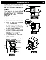
Страница 19: ... Open the door and remove the burn pot by grasping it and pulling straight out Scrape the burn pot with a scraper if necessary Make sure that the burn pot holes are not plugged Empty ashes from the burn pot into the pedestal ash bin through the opening at the bottom of the firebox Put the burn pot back in place Make sure it is level and pushed all the way in e Scrape the ashes in the firebox into ...

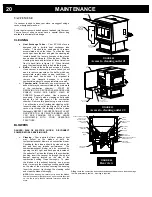
Страница 20: ...utlet and clean thoroughly REPEAT THIS OPERATION AT LEAST ONCE PER TON OF PELLETS BURNED UNTIL YOU ARE FAMILIAR WITH HOW ASHES ACCUMULATE WITH YOUR OPERATING PRACTICES BLOWERS DANGER RISK OF ELECTRIC SHOCK DISCONNECT POWER BEFORE SERVICING UNIT Cleaning Over a period of time ashes or dust may collect on the blades of both the combustion exhaust blower and convection blower Periodically the blowers...

Страница 21: ...orm this service It is also recommended that before each heating season the entire system be professionally inspected cleaned and if necessary repaired To clean the chimney detach the vent at the combustion blower transition where it is attached to the blower RECOMMENDED MAINTENANCE SCHEDULE Use this as a guide under average use conditions Components Daily Weekly or after 10 bags Twice a year or a...

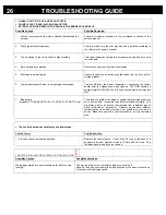
Страница 22: ...lled Check to make sure vent pipe installation meets criteria in owner s manual and pipe manufacturer 4 The airflow pressure switch wire connections are faulty Check the connectors that attach to the airflow pressure switch 5 The airflow pressure switch wires are pulled loose at the connector on the wiring harness Check to see if the wires are loose at the connector 6 Combustion exhaust blower fai...

Страница 23: ...shaft from the auger housing Start by emptying the hopper Take off the top and bottom panels at the back of the stove s body Then remove the auger motor by removing the screws holding the motor to the auger shaft Remove the plate located on the stove body at the bottom of the gear motor to allow the motor to slide out of the stove body Once the motor is out remove the four screws on the steel plat...

Страница 24: ...sor is bad the unit will stop after the ignition cycle If this situation occurs call your dealer or technician 5 The control board is not sending power to the igniter Check the voltage going to the igniter during startup It should be a full current If the voltage is lower than full current check the wiring If the wiring checks out good the board is bad You will need a technician to perform this te...

Страница 25: ... SMOKE SMELL COMING BACK INTO THE HOME Possible Causes Possible Remedies 1 There is a leak in the vent pipe system Inspect all vent pipe connections This is a pressurized exhaust system All vent connector joints must be sealed and fastened in accordance with the pellet pipe manufacturer s instructions to ensure consistent performance and avoid smoke and ash spillage 2 The gasket on the combustion ...

Страница 26: ...mately 3000 RPM You will need a technician to perform this test 7 Bad pellets Applies to GLASS SOOTS UP AT A VERY FAST RATE Only The brand of pellets or the batch of pellets that are being used may be of poor quality If possible try a different brand of pellets You might also want to try a brand that is made from a different type of wood softwood vs hardwood Different woods have different characte...

Страница 27: ...es Inverted polarity in power outlet Power outage Igniter fuse blew up SMOKE SMELL OR SOOT BUILD UP Because it is a wood burning device your ECO 45 may emit a faint wood burning odor If this increases beyond normal or if you notice an unusual soot build up on walls or furniture check your exhaust system carefully for leaks All joints should be properly sealed Also clean your stove following instru...

Страница 28: ...CTION BLOWER HIGH TEMPERATURE SWITCH L 250 MANUAL RESET HIGH TEMPERATURE SWITCH L 250 AUTOMATIC HIGH TEMPERATURE SWITCH F 160 FRESH AIR INTAKE AIR SUPPLY CONTROL PRESSURE SWITCH AUGER MOTOR CLEANING ACCESS PANEL EXHAUST POWER CORD THERMOSTAT TERMINAL COMBUSTION EXHAUST BLOWER MOTOR IGNITER CONVECTION BLOWER AIR SUPPLY CONTROL CONVECTION BLOWER THERMISTOR SWITCH L 250 MANUAL RESET HIGH TEMPERATURE ...

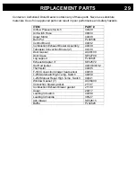
Страница 29: ... Assembly 44039 Tubeaxial Convection Blower 2 44100 Door Gasket AC06100 Door Glass SE52708 Log support PL52691 Exhaust Adapter 3 SE52572 Hot Rod Igniter 44030 44132 Thermistor 44095 F 160 Convection blower heat sensor 44058 L 250 Automatic High Temp Switch 44059 L 250 Manual Reset High Temp Switch 44041 Window Gasket 7 AC06400 Convection blower gasket 21107 Combustion Exhaust blower gasket 21109 A...

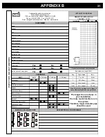
Страница 30: ...vent coming out at the back of the stove on a total distance of 4 feet followed by a Tee and a 6 foot vertical rise it would be acceptable The installation would end be within the allowable configuration zone on the chart since it would have at least one foot of vertical rise for each foot of horizontal run Furthermore the total vertical rise would be at least 3 foot high WARNING To reduce the ris...

Страница 31: ...quivalent vent lenght calculation table DRAW YOUR INSTALLATION 1 SQUARE 1 F00T PART DAILY 10 bags 25 bags E xchanger Baffle Left interior channel Hopper Evacuation blower Blower blades Pressure system Burn pot Convection blower filter Evacuation system Gaskets CLEANING Use 4 pipe if you have more than 15 feet of Equivalent Vent Length EVL The longer the run of pipe in your installation the more re...

Страница 32: ... All parts and labour costs covered by this warranty are limited according to the table below The manufacturer at its discretion may decide to repair or replace any part or unit after inspection and investigation of the defect The manufacturer may at its discretion fully discharge all obligations with respect to this warranty by refunding the wholesale price of any warranted but defective parts Th...

Отзывы: