background image

Drive Test GmbH München 

Handbuch / Manual BIA Class 2 

Seite 18 von 24 

Version 3.1 

Archive: BIA Klasse 2_25N_DE_EN_V3.1 

DESCRIPTION 

3.1 

MECHANIC 

3.1.1  Basic construction 

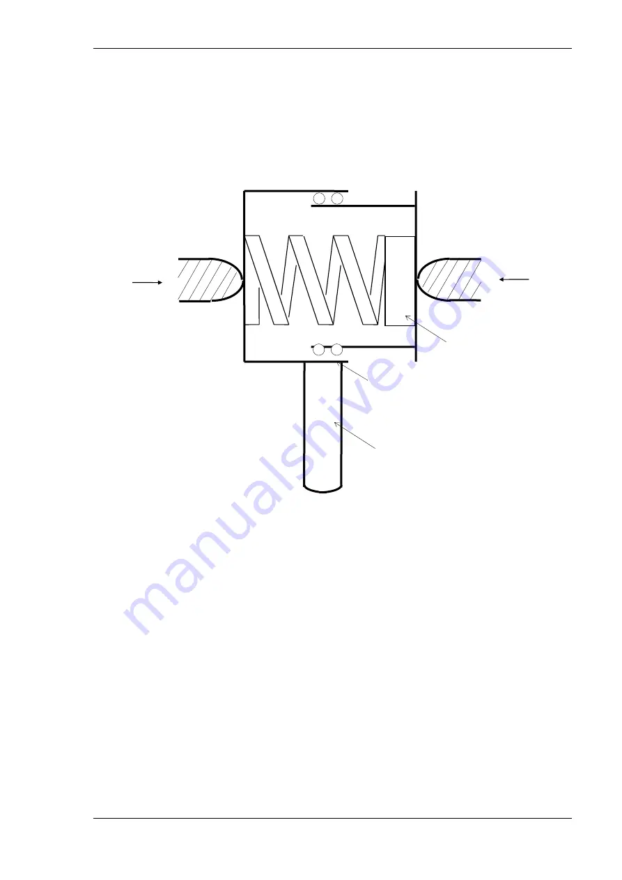
Figure 3: Basic construction 

The instrument consists of a static and a moveable part. Both parts are pressed apart by a 
spring, located between the parts. The spring has a defined stiffness. In order to get a good 
platform quality (i.e. indepence of the force measure result from the location of the force 
initiation), the moveable part is guided by six ball bearings. 

Without load the spring is spanned with about 20 N. The scale ranges from 100 to 750 N. 

Left door edge

Right door edge

spring


Force sensor

mech. guidance

handle

Содержание BIA Class 2

Страница 1: ...BIA Klasse 2 BIA Class 2 25 N mm Mechanisches Schließkraftmessgerät für Bus und Schienenfahrzeuge Mechanic Pinch Force Meter for Bus and Railway Doors Handbuch Manual ...

Страница 2: ......

Страница 3: ...13 INHALT 1 VERWENDUNGSZWECK 4 2 GRUNDLAGEN DER SCHLIEßKRAFTMESSUNG 4 2 1 GESETZE UND NORMEN 5 3 GERÄTEBESCHREIBUNG 6 3 1 MECHANIK 6 3 1 1 Prinzipieller Aufbau 6 3 1 2 Abmessungen 7 4 MESSEN 8 4 1 MESSBEDINGUNGEN 8 4 2 HANDHABUNG DES GERÄTES 8 5 WARTUNG PFLEGE UND KALIBRIERUNG 9 6 SERVICE ADRESSE 10 7 EG KONFORMITÄTSERKLÄRUNG 10 8 TECHNISCHE DATEN 11 ...

Страница 4: ... an fremdkraftbetriebenen Bus und Zugtüren sowie die sinngemäße Verwendung an vergleichbaren Einrichtungen Das Gerät ist vor Nässe zu schützen Über die anwendungsbedingte Beanspruchung hinausgehende Schocks und mech Belastungen 900 N können zur Beschädigung des Gerätes führen 2 GRUNDLAGEN DER SCHLIEßKRAFTMESSUNG Der Verlauf der Einklemmkraft an automatischen Fahrgasttüren ist in Bild 1 schematisch...

Страница 5: ...ppzeigeranzeige und misst deshalb nur die Spitzenkraft Statischer Anteil Nachdem der Türflügel zum Stillstand gekommen ist wirkt nur noch die Kraft des Antriebselementes 2 1 GESETZE UND NORMEN Die oben beschriebenen Messgrößen haben verschiedene biomechanisch bedingte Grenzwerte um die Gefahr von Verletzungen und lebensbedrohlichen Zuständen zu reduzieren In der Bundesrepublik Deutschland trat im ...

Страница 6: ...rden durch eine dazwischen befindliche Feder mit definierter Steifigkeit auseinandergedrückt Um eine möglichst gute Plattformeigenschaft für die Messung zu erhalten Unabhängigkeit vom Einleitungspunkt der Kraft ist die bewegliche Hälfte durch eine Linearführung bestehend aus 6 Kugellagern geführt Im Ruhezustand erzeugt die Feder eine Vorspannung von ca 20 N Der Bereich der Skala reicht von 100 bis...

Страница 7: ...messungen Die beiden Hälften haben zur Krafteinleitung jeweils eine Stempelfläche von 100 mm Durchmesser Der Abstand der Stempelflächen beträgt in entspanntem Zustand 115 mm Der maximal mögliche Weg ist 30 mm d h bei maximaler Kraft beträgt der Abstand der Stempelfächen 85 mm Bild 5 Mechanische Abmessungen in mm 100 115 30 ...

Страница 8: ... Zur Messung hält man das Gerät zwischen die Schließkanten wobei darauf zu achten ist dass die Kraftaufnahmeflächen parallel von den sich schließenden Türflügeln getroffen werden Bei zweiflügeligen Türen ist es sinnvoll das Messgerät mit dem festen Gehäuseteil an einer Türkante anzulegen und bei der Schließbewegung des Türflügels mitzuführen bis das bewegliche Teil des Messgerätes vom anderen Türf...

Страница 9: ...an bei Raumtemperatur ca 20 25 Grad C das Gerät mit dem festen Gehäuseteil nach unten auf eine waagrechte Fläche und belastet es mit einem Gewicht Prüfgewicht 10 kg Anzeigewert 100 5 N 10 kg entsprechen 98 N durch die liegende Lage des Gerätes beim Messen addieren sich ca 225 g Gewicht verursacht durch Gehäuseschale Feder Druckstück Umgerechnet ergibt dies 100 N Wichtig Das Gerät darf nicht zerleg...

Страница 10: ...DRESSE Drive Test GmbH Adi Maislinger Str 9 D 81373 München Germany Tel 7 EG KONFORMITÄTSERKLÄRUNG Wir Drive Test GmbH Hansastr 31 81373 Muenchen Germany Erklären dass das Schließkraftmessgerät BIA Klasse 2 Den Anforderungen der folgenden EG Richtlinien entspricht 2006 42 EC Maschinenrichtlinie Wolfgang Schabel Geschäftsführer ...

Страница 11: ... mm Krafteinleitungsfläche 100 mm Durchmesser Genauigkeit der Federsteifigkeit linienförmige Einleitung 10 10 Überlastschutz ja Gewicht ca 1300 g Masse Rundkörper max Durchmesser 130mm Höhe 115 mm Kraftmessung Bereich 100 750 N Genauigkeit 10 N Auflösung 20 N ermittelter Kennwert Maximalkraft Umgebung 260 x 130 x 115 mm Temperaturbereich 10 bis 30 C Feuchtigkeit max 90 rel F nicht kondensierend ...

Страница 12: ......

Страница 13: ...BIA Class 2 25 N mm Mechanic Pinch Force Meter for Bus and Railway Doors Manual ...

Страница 14: ......

Страница 15: ...F USE 16 2 BASICS OF PINCH FORCE MEASUREMENT 16 2 1 LAWS AND STANDARDS 17 3 DESCRIPTION 18 3 1 MECHANIC 18 3 1 1 Basic construction 18 3 1 2 Mechanical Dimensions 19 4 MEASURE 20 4 1 ENVIRONMENTAL REQUIREMENTS 20 4 2 HANDLING OF THE INSTRUMENT 20 5 MAINTENANCE AND CALIBRATION 21 6 SERVICE ADRESS 21 7 DECLARATION OF CE CONFORMITY 22 8 TECHNICAL DATA 23 ...

Страница 16: ...of power operated bus and train doors or comparable applications The instrument has to be protected from moisture It is designed to withstand normal handling and transporting nevertheless excessive shock or load 900 N can demolish it and should be avoided 2 BASICS OF PINCH FORCE MEASUREMENT A characteristic diagram of a pinch force measurement is shown in figure 1 Figure 1 Characteristic pinch for...

Страница 17: ... the peakforce is possible Static component After the door has been stopped and the reopening system has not instantly opened the door the static component caused of the driving force can be measured 2 1 LAWS AND STANDARDS The characteristic values have as a result of biomechanic considerations certain limits to minimize the danger of human damage In the Federal Republic of Germany in 1989 a law r...

Страница 18: ...ble part Both parts are pressed apart by a spring located between the parts The spring has a defined stiffness In order to get a good platform quality i e indepence of the force measure result from the location of the force initiation the moveable part is guided by six ball bearings Without load the spring is spanned with about 20 N The scale ranges from 100 to 750 N Left door edge Right door edge...

Страница 19: ...EN_V3 1 3 1 2 Mechanical Dimensions The force is initiated on areas on both sides of 100 mm diameter each In rest position the distance between the right and left initiation area is 115 mm The maximum displacement is 30 mm i e the minimum area distance is 85 mm Figure 4 Mechanical dimensions in mm 100 115 30 ...

Страница 20: ...ter to the origin of the scale For measuring put the instrument between the closing edges Be careful to contact the initiation area in parallelum to the closing edges When testing doors with two moving wings you are recommended to press the static part of the instrument to one wing and follow the moving door until the other wing contacts the moveable part of the instrument Be careful not to tilt t...

Страница 21: ...5 degrees centigrade Place it with the fixed part of the housing on a horizontal plane and put the test weight on it weight 10 kg indication 100 5N 10 kg are equivalent to 98 N due to the measure position 225 gr have to be added caused by case spring etc The resulting weight is equivalent to 100 N Important The instrument should not be disassembled because the basic adjustment is lost In case of a...

Страница 22: ...Archive BIA Klasse 2_25N_DE_EN_V3 1 7 DECLARATION OF CE CONFORMITY We Drive Test GmbH Hansastr 31 81373 Muenchen Germany declare that the Pinch Force Meter BIA Class 2 meet the intend of the applicable EC directives 2006 42 EC Machinery Directive Wolfgang Schabel Managing Director ...

Страница 23: ... rates 25 N mm Gap width 115 mm Force initiation area 100 mm Durchmesser Precision of spring deflection rate 10 10 Overload protection yes Weight ca 1300 g Measures Round body max Diameter 130mm Height 115 mm Force Measurement Range 100 750 N Accuracy 10 N Resolution 20 N Enviroment 260 x 130 x 115 mm Range of Tempreture 10 bis 30 C Humidity max 90 rel F not condensing ...

Страница 24: ......

Отзывы: