Service Manual
rev 5.0 with software Ind1V022
2 INSTALLATION
2.1 Cubicles
Inverter is delivered with external braking resistors.
See drawings of resistors for sizing.
2.2 Braking
resistor
See design drawings
2.3 Power
cabling
2.3.1 Shielded motor cable
In crane application inverter fulfils EN61800-3/A11 (IEC 1800-3) second environment radiated emission
requirements without shielded motor cable.
In the second environment, shielded motor cable is recommended to use in fixed installations, especially in
buildings. However motor cables in crane and festoon power supplies are normally not shielded due to the
practical reasons.
Shielded motor cable is essential to use if installation is requested to fulfil the first environment emission
requirements.
2.3.2 Double
collectors
If the power is supplied to the crane via conductor rails, double collectors are needed. This ensures a reliable
contact with the rail in all circumstances. Short interruptions and sparks between the conductor rail and the
collector may cause nuisance tripping, other undesired operations and in worst case even permanent damage
to components.
2.3.3 Cable
selection
Cabling for inverter can be done using normal crane cables. All the cables must be dimensioned according to
local regulations. Ambient temperature, cabling method (size of bunches etc.) and allowable current for the
cable in use must be taken into consideration. If there are no other regulations, following values can be used
(three phase 400V supply).
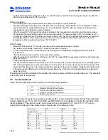
The table below is based on ED
≤
60% and ambient tempe40°C (104°F). A higher ambient
temperature may require increased cable sizes. The input current does not exceed the continuous current
(Icont) of inverter, so it is selected to be the dimensioning current. If the actual load current is below inverter
continuous current, then the fuses and the supply cable may be dimensioned according to the load current.
Power
class
002 003 004 005 007 011 015 018 022
Continuous current
I
CONT
A
6.5 8 10 13 18 24 32 42 48
Fuse
A
10 10 10 16 20 25 35 50 50
Max motor cable length
m
50 50 50 50 50 50 50 50 50
Ft
160 160 160 160 160 160 160 160 160
Motor cable
40
o
C mm
2
1.5 2.5 2.5 2.5 4 6 10 10 10
104
o
F AWG
14 14 14 12 10 10 8 8 6
Braking resistor cable
40
o
C mm
2
2.5 2.5 2.5 2.5 2.5 2.5 2.5 4 4
104
o
F AWG
14 14 14 14 14 14 14 12 12
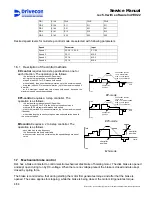
Power
class
030 037 045 055
11/58
Drivecon Inc. reserves the right to alter or amend the above information without notice.
Содержание D2L
Страница 59: ......


