background image

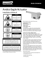
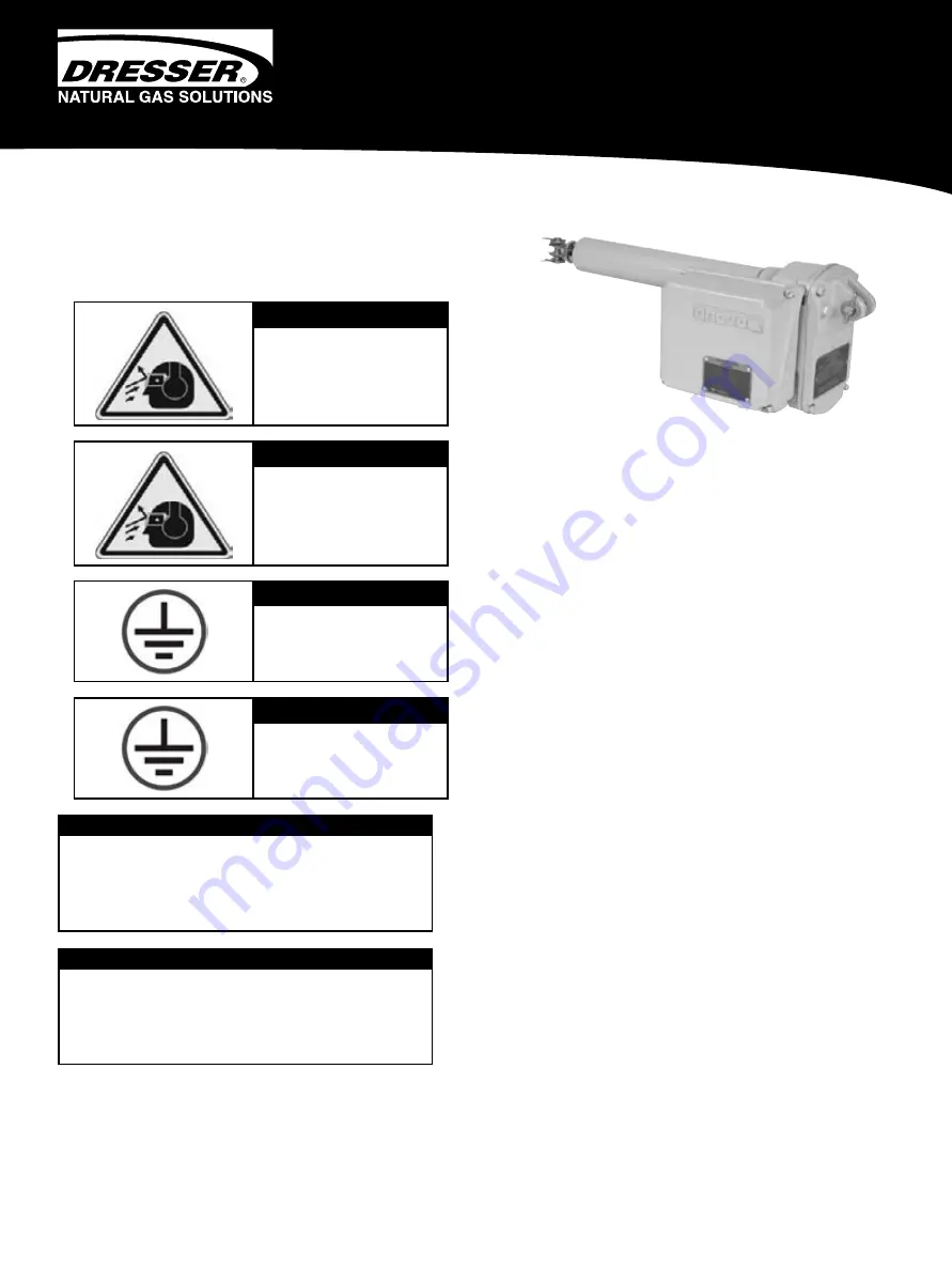
Andco Eagle Actuator

Installation Manual

Refer all questions not covered in this manual to: 

Industrial Products Group

Andco Actuators

16240 Port Northwest Drive

Houston, TX 77041

T: 832-590-2306

Toll Free: 1-800-945-9898
F: 713-849-2879

Be sure to include the model and serial number located on the 
nameplate of your Eagle actuator in all communications and 
parts orders. The nameplate is located on the gear housing cover. 
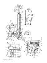
Numbers in brackets refer to item number in figure 2 on page 8.

Intent of Usage/Application

Dresser Natural Gas Solutions (NGS) Andco electric linear 
actuators offer a superior choice when reliable, precise, controlled 
motion is required. Whether moving industrial doors, providing 
accurate positioning feedback for antennas, or modulating 
and controlling louver dampers, customers can rely on Andco 
actuator solutions.

The Andco Eagle actuators include weatherproof and dustproof 
units, offering customers durability and performance in severe 
industrial environments, including hot and cold temperature 
extremes. Andco Actuators are a superior solution for a range of 
functions including positioning, lifting/lowering, pushing/pulling, 
and opening/closing.

Andco actuator technology offers low maintenance packages 
with internal adjustable limit switches for on/off controls and 
light indication, optional internal position/process controls for 
positioning, and motor control. Our actuator solutions deliver 
ease of installation, maintain constant output force and velocity, 
and consume power only during movement.

These actuators feature:

•  High-starting torque motor with thermal overload protection

• Non-rotating extension rod

• Non-back driving acme screw 

• All metal gearing

The information contained in this manual is essential 

to safe, successful, long term operation of your Andco 

Eagle linear actuator. Read and follow the requirements 

concerning storage, installation and adjustments. Failure 

to do so could void the warranty covering your actuator.

NOTICE

WARNING

PPE

Approved Personnel Protective 

Equipment for the site must  

be worn.

WARNING

GROUNDING LUG

Unit must be grounded with 

minimum size 10 AWG wire.

AVERTISSEMENT

EPI

Il convient de porter un 

équipement de protection 

individuelle sur le site.

AVERTISSEMENT

PATTE DE MISE À LA TERRE

L’unité doit être mise à la terre 

avec un fil de calibre 10 au moins.

Les renseignements contenus dans ce manuel sont essentiels 

au fonctionnement sûr, efficace, durable de votre actionneur 

linéaire Andco Eagle. Lisez et respectez les exigences relatives au 

stockage, à l’installation et aux réglages. Le non-respect de ces 

exigences peut annuler la garantie couvrant votre actionneur.

AVIS

This manual gives instructions for storing, installing, operating and 
servicing the Model 3100 Eagle linear actuator.

Andco Actuators

Содержание 3100

Страница 1: ...ntrols and light indication optional internal position process controls for positioning and motor control Our actuator solutions deliver ease of installation maintain constant output force and velocity and consume power only during movement These actuators feature High startingtorquemotorwiththermaloverloadprotection Non rotating extension rod Non back driving acme screw All metal gearing The info...

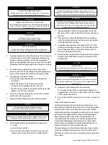
Страница 2: ...is not recommended that the control compartment cover be positioned face down In order to maximize seal integrity the unit should be mounted with the extension rod pointed up vertical installations or with motor on top horizontal installations NOTICE 1 The body tube adapter 57 is used for face flange or trunnion type mounting 2 The actuator can be clevis mounted utilizing the clevis 29 in the exte...

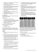
Страница 3: ... wiper 2 verify that the alignment between the actuator mounting support and the driven equipment places no side loading on the extension rod 6 at any point throughout the full stroke length Refer to Figure 2 on page 7 4 Do not hammer or gouge the outside surface of the extension rod 6 This may damage the plating integrity or cause surface irregularities which can damage rod seals 5 Face flange or...

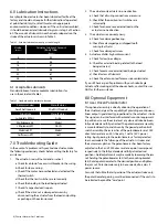
Страница 4: ...mit switch 52 lever 6 Repeat steps 4 and 5 to set the retract limit switch utilizing the slotted shaft 49 limit switch 53 and cam 51 Turn the motor shaft in a counterclockwise direction 7 Replace the motor pipe plug 46 8 Replace the limit switch compartment cover 38 9 Re energize electrical power to the actuator If damaged replace the complete geared position limit switch assembly rather than atte...

Страница 5: ...uit 2 A selector switch marked to indicate the test potential or 3 A marking in a readily visible location to indicate the test potential for test equipment having a single test potential output In cases 2 and 3 the test equipment shall include a lamp or other visual means to indicate that the test potential is present at the test equipment output 5 All test equipment shall be maintained in curren...

Страница 6: ...sted so the 0 and 1000 ohm resistance points correspond respectively to the fully extended and fully retracted rod positions Field adjustments may be made by loosening the jam nut holding the potentiometer 64 to the mounting bracket 65 Rotate potentiometer to the desired position and tighten the jam nut Potentiometer only to be connected to a class II power source For units that utilize the last p...

Страница 7: ...AWING IS THE SOLE PROPERTY OF GE OIL GAS AND MAY NOT BE USED REPRODUCED PUBLISHED OR DISCLOSED TO OTHERS WITHOUT EXPRESS AUTHORIZATION THEREOF IT SHALL BE RETURNED TO THE OWNER UPON DEMAND PROPRIETARY AND CONFIDENTIAL INTERPRET P THIRD ANGL ASSEMBLY DESCRIPTION GE Oil Gas UNLESS OTHERWISE SPECIFIED MATERIAL WEIGHT REMOVE BUR MACHINED FI PRPSHEET Material DIMENSIONS ARE IN INCHES CHAMFERS AND FILLE...

Страница 8: ...8 Dresser Natural Gas Solutions Figure 2 Eagle Actuator Parts Drawing ...

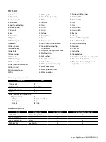
Страница 9: ...x nut 19 Main drive gear 20 Unassigned 21 Gear compartment cover 22 Unassigned 23 Intermediate gear 24 Pin 25 Motor gasket 26 Actuator body housing 27 Motor 28 Jam nut 29 Clevis 30 O ring 31 O ring 32 Fastener 33 Nameplate 34 Screw 35 Seal washer 36 Position limit switch assembly 37 Capacitor terminal strip sub assembly 38 Limit switch compartment cover 39 Machine screw 40 Lock washer 41 Socket he...

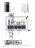
Страница 10: ...am came with your units before you work on the actuators 1 2 DO NOT PERFORM HI POT TEST ON TERMINAL BLOCK LOCATIONS 10 11 12 CUSTOMER ALTERNATIVE FOR OPTIONAL DRY CONTACTS DETAIL A 1 2 3 4 CAPACITOR CONNECTIONS WITH OPTIONAL SERIES WIRE RESISTOR DETAIL C STANDARD CAPACITOR CONNECTIONS DETAIL B LEGEND E E 7 7 4 3 3 ...

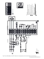
Страница 11: ...agram for three Phase Please refer to the wiring diagram came with your units before you work on the actuators LEGEND 1 2 DO NOT PERFORM HI POT TEST ON TERMINAL BLOCK LOCATIONS 10 11 12 CUSTOMER ALTERNATIVE FOR OPTIONAL DRY CONTACTS DETAIL A 1 2 3 4 E E E 7 7 7 7 4 3 3 ...

Страница 12: ...24 30 and 36 inches Speed and Force Velocity in sec Force lbs Breakaway Running 0 2 2000 1000 0 4 1500 750 0 8 750 340 2 0 500 200 Duty Cycle 25 Certifications North America C2D1 Groups E F and G Dust Ignition Proof T5 Type 4 Watertight CSA Certificate US Certificate CSA C22 2 No 0 ANSI UL 61010 1 CSA C22 2 No 25 UL50 and UL50E CSA C22 2 No 94 FM 3600 and FM3616 CSA C22 2 No 142 Mounting Types Cle...

Страница 13: ...Andco Eagle Actuator IOM NGS IPG 0031 13 ...

Страница 14: ...14 Dresser Natural Gas Solutions ...

Страница 15: ...Andco Eagle Actuator IOM NGS IPG 0031 15 ...

Страница 16: ...the right to make changes in specifications and features shown herein or discontinue the product described at any time without notice or obligation Contact your Dresser Natural Gas Solutions representative for the most current information The Dresser Logo and all Trademarks containing the term Dresser are the property of Dresser LLC a subsidiary of Baker Hughes a GE Company www dresserngs com Andc...

Отзывы: