background image


6. 

CONNECTING A HEATER TO A HOT WATER DISTRIBUTION 

 
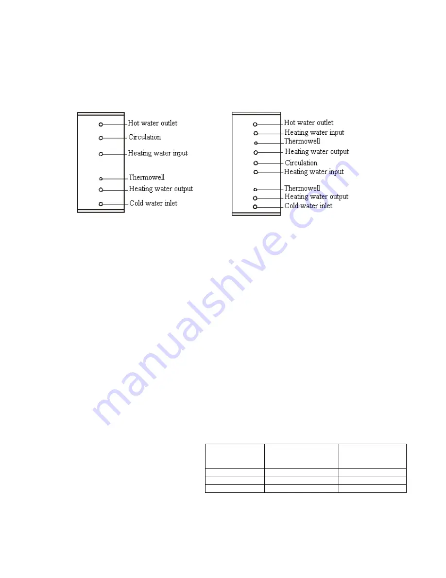
Implement the connection in accordance with scheme on page 6.


Scheme of Heater's Water Inputs and Outputs 


OKC 800 NTR/1 MPa 

OKC 800 NTRR/1 MPa 


OKC 1500 NTR/1 MPa 

OKC 1500 NTRR/1 MPa 


OKC 2000 NTR/1 MPa 

OKC 2000 NTRR/1 MPa 


The heater’s cold water inlet must be fitted with a T-fitting with a discharge valve for any discharge of water from the 
heater (see Section No.11). 
On  the  hot  water  inlet,  each  individually  closable  heater  must  have  a  test  cock,  backflow  valve,  safety  valve,  and  a 
manometer. 


7.


SECURITY EQUIPMENT


Each  hot  service  water  pressure  heater  must  have  a  safety  valve  with  a  backflow  flap.  Nominal  clearance  of  safety 
valves is defined in the ČSN 06 0830 standard. The 300 l heaters are not equipped with a safety valve. The safety valve 
must be easily accessible, as close to the heater as possible. The inlet pipes must have at least the same clearance as the 
safety  valve.  The  safety  valve  is  placed  high  enough  to  secure  dripping  water  drain  by  gravity.  We  recommend 
mounting the safety valve onto the branch led above the heater. This allows easier exchange without having to drain the 
water  from  the  heater.  Safety  valves  with  fixed  pressure  settings  from  the  manufacturer  are  used  for  the  assembly. 
Starting pressure of a safety valve must be identical to the maximum allowed heater pressure, and at least 20 %  higher 
than the maximum pressure in the water main. If the water main pressure exceeds such value, a reduction valve must be 
added to the system.


No stop valves can be put between the heater and the safety valve. During the assembly, follow the 

guide provided by the safety equipment manufacturer. Before putting the safety valve into operation it always needs to 
be  checked  by  manual  removal  of  the  membrane  from  the  valve  seat  and  turning  the  make-and-break  device  button 
always in the direction of the arrow. After being turned, the button must click back into a notch. Proper function of the 
make-and-break  device  results  in  water  draining  through  the  safety  valve  outlet  pipe.  In  common  operation,  such  a 
check needs to be implemented at least once a month, and after each heater shutdown for more than 5 days. Water can 
drip from the safety valve through the drain pipe; the pipe must be freely open to the atmosphere, placed vertically and 
shall be in an environment free of temperatures below freezing. 


When draining the heater, use a recommended drain 
valve. First, close water input into the heater.


Find necessary pressure values in the following table.  
 
For  proper  safety  valve  operation,  a  backflow  valve 
must  be  mounted  on  the  inlet  pipes,  preventing 
spontaneous  heater  draining  and  hot  water 
penetrating back into the water main. 


When assembling the security equipment, follow ČSN 06 0830. 

Safety valve 

starting pressure 

(MPa)


Admissible operating 

water heater 

pressure (MPa)


Max. pressure in 

the cold water pipe 

(MPa)


0.6 

0.6 

up to 0.48 

0.7 

0.7 

up to 0.56 

up to 0.8 

Содержание OKC 1500 NTR/1Mpa

Страница 1: ...Pa OKC 800 NTRR 1 MPa OKC 1500 NTR 1 MPa OKC 1500 NTRR 1 MPa OKC 2000 NTR 1 MPa OKC 2000 NTRR 1 MPa Družstevní závody Dražice strojírna s r o Works Cooperative Dražice Machine Plant Ltd Dražice 69 29471 Benátky nad Jizerou Tel 326 370911 fax 326 370980 www dzd cz dzd dzd cz ...

Страница 2: ...junction with another source of heating water most often a gas boiler The NTRR types combine two sources of heating water gas boiler a solar system or a heat pump Their nominal performance provides sufficient amount of hot water for large flat units premises restaurants and similar establishments In case of increased hot water consumption these tanks heat water continuously operating similarly to ...

Страница 3: ...in case of a combined heater We recommend you operate the heater with one type of energy In case a solar system is connected to the bottom exchanger it is necessary to connect a TJ 6 4 line element in the coupling above the heater for potential additional heating 4 PUTTING THE HEATER INTO OPERATION After connecting a heater to the water main the hot water heating system the electric network and af...

Страница 4: ...erature C 110 110 110 Max hot water temperature C 95 95 95 Heating surface of the bottom top exchanger m 2 2 76 1 2 3 5 1 75 4 2 0 Bottom top exchanger performance for temperature drop 80 60 C kW 36 4 19 2 38 9 26 4 71 5 41 9 Hot water1 permanent performance bottom top exchanger l hr 627 330 670 454 761 503 Heating time by bottom top exchanger for temperature drop 80 60 C min 70 60 128 94 155 108 ...

Страница 5: ...ast 20 higher than the maximum pressure in the water main If the water main pressure exceeds such value a reduction valve must be added to the system No stop valves can be put between the heater and the safety valve During the assembly follow the guide provided by the safety equipment manufacturer Before putting the safety valve into operation it always needs to be checked by manual removal of the...

Страница 6: ...emises Premises with tub or shower to hot service water heating system c to the hot water heating system ČSN 06 0320 Thermal systems in buildings Hot water preparation Design and Project Engineering ČSN 06 0830 Thermal systems in buildings Protecting devices ČSN 73 6660 Internal water mains ČSN 07 7401 Water and steam for thermal energy equipments with working steam pressure up to 8 MPa ČSN 06 101...

Страница 7: ...eated by a gas boiler and solar collectors controlled by a three way valve An example of a group heater connection for steady hot water consumption from all tanks using Tichelmann s method OV Heating water TUV Hot service water SV Cold water 1 Return valve C Circulation 2 Pump ...

Страница 8: ... time by exchanger for temperature drop 80 60 C min 262 155 86 73 Performance for temperature drop 80 60 C kW 28 9 44 2 71 5 81 4 Permanent performance l hr 498 761 1230 1400 2000 NTRR top exchanger surface 2 00 m2 Heating time by exchanger for temperature drop 80 60 C min 160 108 70 63 Performance for temperature drop 80 60 C kW 21 2 29 2 41 9 46 3 Permanent performance l hr 364 503 721 797 NL Po...

Страница 9: ...eater was delivered The service fee was paid pursuant to Act No 477 2001 Coll as amended at EKO KOM a s The client number of the company is F06020274 Take the water boiler packages to a waste disposal place determined by the town When the operation terminates disassemble and transport the discarded and unserviceable heater to a waste recycling centre collecting yard or contact the manufacturer 1 1...

Страница 10: ...ection of the arrows to put the two insulation sides together so that see Fig 1 the openings in the insulation fit the boiler inlets and outlets It must be secured that both halves of the closure are not further than 20 mm apart before closing see fig 2 No foam shall get into the zip fastener on closing After the insulation coat is properly mounted and the closure closed insert the top lid made of...

Страница 11: ...11 15 CONSTRUCTION HEATER PARAMETERS OKC 800 NTR 0 6 MPa OKC 800 NTRR 0 6 MPa ...

Страница 12: ...B 442 452 C 1117 1152 D 1100 1200 d 1000 1100 E 1217 1252 F 1825 1997 G 437 447 H 1167 1202 I 1354 1472 J 1494 1612 K 1825 1997 OKC 1500 NTRR 1 MPa OKC 2000 NTRR 1 MPa A 2240 2430 B 442 452 C 1067 1090 D 1200 1300 d 1000 1100 E 1217 1252 F 1342 1393 G 1722 1713 H 1825 1997 I 437 447 J 1167 1202 K 1354 1472 L 1494 1612 M 1825 1997 ...

Отзывы: