220 V Micro Projector Lift by Draper, Inc.
page 3 of 4
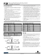
Low Profile Aero Lift Bracket
* Projector-specific bracket height varies according to the
projector model. Contact Draper, Inc. for details.
Installing Projector
Generally, the video projector should be suspended from the bottom pan
according to projector manufacturer’s instructions or using optional Low
Profile Aero Lift Bracket. If the Low Profile Aero Lift Bracket is used, holes are
pre-drilled for attachment.
If for any reason the hole placement must be changed, completely lower
Micro Projector Lift before attempting to drill new holes.
The Micro Projector Lift has a grounded 220 V a.c., 50Hz power cord for
projector power supply. The power cord is laced down the back scissor and is
“hot” at all times. Control cables (maximum of four) should be laced through
our Cable Management System (back scissor only—see method used for
power cord). This will ensure that cords do not become tangled and damaged
during Micro Projector Lift operation.
Unit and projection system should be operated, checked and adjusted as
necessary at this time (see below for limit adjustment procedures).
Warning:
Keep fingers & other objects away from ceiling closure & scissor
mechanisms when unit is operating. Serious injury or damage can result.
Installing Ceiling Closure
If your Micro Projector Lift is equipped with a ceiling closure system, it can be
used as is, or in conjunction with a square of existing ceiling tile.
Please refer to diagram at right for these instructions.
➀
If installing with ceiling tile, you may need to cut tile so that its overall
dimensions are the same as (or slightly less than) the closure panel. Place
tile into trim frame. Lay closure panel on top (back side) of ceiling tile, and
tighten screws to hold in place.
➁
Attach
5
/
16
"-18 threaded rods to pem nuts in lift pan.
➂
Run unit “up” until bottom pan stops at highest position. Mark position on
5
/
16
"-18 rods even with ceiling level and cut rods to length (removing
from pan if convenient).
➃
Run unit “down” until bottom pan stops at “show” position.
➄
Attach closure to lower end of
5
/
16
"-18 rods by slipping into four corner
slots and secure with nuts above and below slots.
➅
Run unit “up” again to highest position. Measure distance by which panel
fails to reach required “closed” height for surrounding ceiling.
➆
Run unit “down” then readjust mounting of
5
/
16
"-18 rods in traveling grid
to raise panel required distance.
➇
Test unit operation to confirm that panel will stop in closed position just
before touching ceiling.
NOTE:
Immediately upon completion of the surrounding ceiling, units should
be operated to confirm that optional ceiling closure panel stops just short of
touching ceiling in closed position.
Adjustments
CAUTION:
Be sure all switches are in “off” position before adjusting limit
switches. Always be prepared to shut lift off manually when new adjustment is
being tested.
Please refer to diagram at right for these instructions.
Limit switches for the Micro Projector Lift are preset at the factory. The “Up”
(closed) limit switch is set for fully closed. The “down” limit switch is set for
fully lowered (1219 mm). Once unit is in place, the “down” limit switch may
need to be changed to stop the Micro Projector Lift closer to the ceiling (that
is, to raise the “down” position). Limit switches are located on the left end of
roller (as seen from the front, or non-scissored end, of the unit) and are
accessible to a screwdriver/Allen wrench (
5
/
32
").
Adjusting Down Position —
“Down” position may be adjusted by turning
limit switch adjustment socket number 1. Turning the socket clockwise will
stop the Micro Projector Lift closer to the ceiling. Turning it counter-clockwise
will cause the lift to stop at a lower point.
Adjusting Up (closed) Position —
Because the “up” (closed) position is
preset at the factory, Draper does not recommend changing this position
using the limit switch. The “up” position of the closure may be changed by
changing the length of threaded rod (see instructions for closure installation
below). If necessary, however, “up” position may be adjusted by turning limit
switch adjustment socket number 2. Turning the socket counterclockwise
creates a higher, or more fully closed position. Turning it clockwise creates a
lower ‘UP” (closed) position.
Caution: Do not set limit switch so that the MPL motor is still running
after the lift is closed. This could result in damage to the motor.
Terminal
Strip
Up (closed)
Limit Switch
Down (open)
Limit Switch
Rear
Scissor
Left
Scissor
1
2
+
-
+
-
81 mm
*


