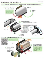
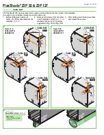
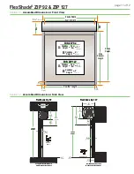
background image

C

H

A

N

N

E

L

S

I

D

E
C

H

A

N

N

E

L

A

D

A

P

T

O

R

CE

ILI

NG

CEIL

ING

sha

de

W

A

L

L

END

CAP

HEADBO

X

W

A

 L

 L

W

A

 L

 L

CUT into 

SQUARES

Foam 

Padding

C054.2218

1.5"

(38mm)

W

A

 L

 L

W

A

 L

 L

Section 8 -

 Mounting Side Channels Into a Recessed Pocket 

(Optional)

W

A

 L

 L

W

A

 L

 L

si

de

ch

a

n

nel

cov

e

r

W

A

 L

 L

W

A

 L

 L

W

A

 L

 L

W

A

 L

 L

si

de

ch

a

n

nel

cov

e

r

W

A

 L

 L

W

A

 L

 L

5.


 Re-attach the Side 

Channel Cover and 

secure with screws 

removed in Section 5 

(Installing Side Channels)

.

6.


 Repeat Steps 1-5 at the 

remaining Side Channel 

mounting location.

Please Note:

 Installer is 

responsible for providing 

space and clearance to mount 

headbox above wall structure.

W

A

 L

 L

W

A

 L

 L

2" 

(51mm)

‘C’ C

han

nel 

C09

0.0

61

1.


 Insert provided 'U' Channel 

(PN: C090.061)


into recessed cavity in building structure. 

Secure the 'U' Channel using appropriate 

hardware 

(by others)

.

Please Note:

 Installer is responsible for selecting 

mounting hardware appropriate for site conditions.

2.


 Cut foam strips 

(provided)

 into 1.5" 

(38mm)

 squares and attach them 

to the 'U' Channel at all desired 

mounting points of the Side Channel.

W

A

 L

 L

W

A

 L

 L

CUT into 

SQUARES

Foam 

Padding

C054.2218

1.5"

(38mm)

3.


 Place the modified Side 

Channel into the 'U' Channel 

and secure it to the building 

structure using appropriate 

mounting hardware 

(by others)

Please Note:

 Max. spacing between 

fasteners is 24" 

(610mm)

.

Side Channel Mounting Hardware 

(by others)

 should go through center 

of Foam Padding, through 'U' 

Channel and then into the wall.

W

A

 L

 L

W

A

 L

 L

4.


 Reinsert the Fabric 

Retainer Strip.

Attach 

Foam 

Padding  

at every 

Side 

Channel 

Mounting 

location.

NOTE: 

Installer MUST provide a 

recessed pocket at the top of 

the channel large enough to 

allow for headbox installation 

and accommodate hem bar 

and fascia install/removal.

Specific Fastener 

locations are 

determined by 

installer.

Please Note:


Max. spacing 

between fasteners 

is 24" 

(610mm)

.

PLEASE NOTE:

 Channel Adaptor 2" U Channel option MUST be ordered for the 

channel to be provided with unit — it is not provided standard.

Section 9 -

 Channel Adaptors 

(Optional)

If the opening is not suitable for direct mounting 

either component due to uneven surfaces, 

stonework, trim, or other irregular element, use 

Channel Adaptors to build in or fur out an opening 

to enable Side Channel or headbox attachment.

Channel Adaptors can provide a mounting 

surface for both the Side Channels and headbox. 

If necessary, installer can "stack" a sufficient 

number of tubes to bring the opening flush from 

floor to ceiling.

Use and configuration of Channel Adaptors is site 

dependent: each installation may require different 

adaptors or a combination of adaptors. Installer 

is responsible for safely and securely attaching 

Channel Adaptors to prepare each opening for 

best installation of the product. 

STA

CKI

NG 

CHA

NNE

L AD

APT

ORS 

TO MO

DIF

Y SP

ACE

C073.002

C090.053

C104.148

C090.054

C090.061

Section 10 -

 Anti-Insect 

Brush Seals 

(Optional)

The FlexShade

®

 ZIP has optional 

Anti-Insect Brush Seals pre-installed 

along the width of the fascia. The 

brush seals supplied for each of the 

side channels need to be installed.

Insect Barrier 

Brush Seal

TOP O

SIDE 

CHAN

NEL

Remove the double-sided tape 

and apply to the side channels.

page 7 of 12

FlexShade

®

 ZIP 92 & ZIP 127

Содержание FlexShade ZIP 127

Страница 1: ...ont View 11 Section 17 Assembled Dimensions Side View 11 Section 18 Component Dimensions 12 POWER DRILL PENCIL 2 1 TAPE MEASURE HARDWARE by others LEVEL PLIERS CRIMPING TOOL WIRE STRIPPERS CAUTION Read and understand all warnings before beginning installation LASER LEVEL HEX WRENCH TOOLS REQUIRED PERSONNEL REQUIRED HEADBOX SHADE FABRIC MOUNTING BRACKETS Wall Mount shown HEM BAR END CAP SIDE CHANNE...

Страница 2: ...headboxes pockets wall clips and other hardware must be installed level Unit must be level and square 6 Never leave the area while operating the unit during installation maintenance or normal operation unless it is secure and safe 7 Before testing or operation carefully inspect the entire area and path of the shade and areas underneath the shade to be sure no persons or objects are in the area 8 T...

Страница 3: ...bracket USE ALL FOUR 4 mounting holes Fig 3 B 2 Attach Headbox to brackets and tighten Set Screws Fig 3 B 3 Mount the Side Channels Section 5 Caution Hem Bar does not retract into the Headbox Provide at least 21 4 57mm clearance if mounting over a swinging window or door 3 Mounting Brackets MUST be installed with a gap of 13 4 44mm between the Endcap and the Mounting Bracket edge Fig 1 Mark wall j...

Страница 4: ...ce using appropriate fasteners WALL MOUNT HOLES CEILING MOUNT HOLES 1 Using the mounting holes in the endcaps as a guide drill pilot holes on both ends of the Headbox Please Note Installer is responsible for selecting mounting hardware appropriate for site conditions B C E A Figure 4 B Figure 4 C 3 Remove Roller Assembly 4 Proceed to Section 4 Please Note Leave a 1 44mm gap between Endcap and Moun...

Страница 5: ...h Side Channel covers may result in product failure in high wind 3 Drill Side Channels at desired mounting points Fig 6 B 4 Mark wall or jamb and drill small pilot holes in mounting surface Please Note Recommended attachment of Side Channel to structure is minimum of every 24 61cm 1 Use 1 8 3 mm Hex Key to remove Screws from Side Channels and Side Channel Covers Fig 6 A Please Note Do NOT remove t...

Страница 6: ...alled in a pocket in ceiling Please Note Be sure to provide adequate clearance for removal of Roller Assembly during installation and maintenance Minimum depth of ceiling pocket is 6 159mm Side Channel Side Channel FABRIC RETAINER STRIP ZIPPER HEM BAR WALL FlexShade ZIP 92 4 121mm 3 92mm 5 149mm 3 92mm min 1 32mm min 6 159mm REMOVE FASCIA 5 Reinsert Fabric Retainer Strips into Side Channels and re...

Страница 7: ... Strip Attach Foam Padding at every Side Channel Mounting location NOTE Installer MUST provide a recessed pocket at the top of the channel large enough to allow for headbox installation and accommodate hem bar and fascia install removal Specific Fastener locations are determined by installer Please Note Max spacing between fasteners is 24 610mm PLEASE NOTE Channel Adaptor 2 U Channel option MUST b...

Страница 8: ...ns until motor moves down then release Use UP and DOWN buttons to move shade to correct lower limit and press MY STOP 4 While motor is at lower limit hold UP and MY STOP buttons until motor moves up then release The shade should move to upper limit and stop 5 Next hold MY STOP button for five seconds until motor jogs 6 Put motor into USER MODE by pressing small programming button Fig 9 on the back...

Страница 9: ...imit switch must be set prior to connecting to system Motor must be installed so limit switches are pointed up or accessible 7 Operate shade to desired down stop position Set limit by turning proper socket toward to lower limit and to raise it 8 Operate shade to desired up stopping position Set limit by turning proper screw toward to raise limit and to lower it Please Note Each full rotation of th...

Страница 10: ...igure 10 A CABLE EXITS HEADBOX 92 Figure 10 B CABLE EXITS HEADBOX 127 9 5mm 13mm 22mm 1 25mm Cable Exit TOP TOP BACK 13mm ENDCAP F R O N T F R O N T 9 5mm 13mm 1 30mm Cable Exit BACK TOP BACK 13mm ENDCAP F R O N T F R O N T F R O N T 1 44mm 1 32mm Cable Exit SIDE TOP BACK 31 8mm 40 10 2mm OR END CAP F R O N T 1 33mm 1 33mm 22mm 13mm 9 5mm 1 35mm Cable Exit TOP TOP BACK END CAP 31 8mm 40 10 2mm OR ...

Страница 11: ...5 149mm Headbox Height B 3 92mm Headbox Height A FOR ZIP 127 Hem Bar 7 184mm Headbox Height B 5 127mm Top View Down Top View Down SHADE HEIGHT SHADE HEIGHT Wall Mounted Headbox with Wall Mounted Side Channels Ceiling Mounted Headbox with Jamb Mounted Side Channels FlexShade Zip 92 FlexShade Zip 127 5 148mm 3 92mm 2 57mm 1 41mm 7 184mm 2 57mm 1 41mm 1 41mm 5 127mm 5 127mm 3mm 3 92mm 3mm page 11 of ...

Страница 12: ...de ZIP 92 Curved Headbox FlexShade ZIP 92 Square Headbox 5 127mm 5 127mm 5 127mm 5 127mm 5 127mm FlexShade ZIP 127 Curved Headbox FlexShade ZIP 127 Angled Headbox FlexShade ZIP 127 Square Headbox 1 41mm 9 5mm 1 41mm 19mm 2 51mm 1 25mm Side Channel Hem Bar Optional Channel Adaptors 1 38mm 1 38mm 2 4mm 19mm C073 002 6mm 1 29mm 1 41mm 19mm 1 6mm 9 5mm C090 053 3mm 1 32mm 1 38mm C104 148 1 29mm 1 41mm...

Отзывы: