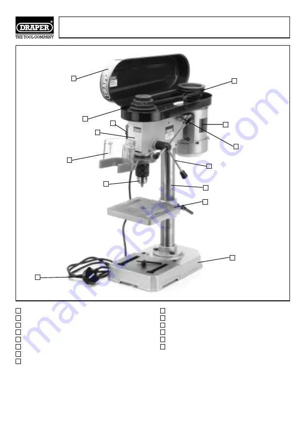
Draper D13/5A Скачать руководство пользователя страница 8

TABLE
COLUMN
BASE
ON/OFF SWITCH
DRIVE BELT/TENSION ADJUSTER
MOULDED PLUG AND CABLE

MOTOR
PULLEY COVER
MOTOR PULLEY
SPINDLE PULLEY
SPECIFICATION LABEL
DOWN FEED ASSEMBLY
CHUCK GUARD
CHUCK

KNOW YOUR BENCH DRILL

- 8 -

I

J

K

L

M

N

A

B

C

D

E

F

G

H

I

J

K

L

M

N

A

B

C

D

E

F

G

H

Содержание D13/5A

Страница 1: ...and safe use We recommend that this manual is read before any operation of the machine before performing any kind of adjustment to the machine and prior to any maintenance tasks By following all the...

Страница 2: ...ce to BS EN 61029 1996 JOHN DRAPER Managing Director 31 05 99 DECLARATION OF CONFORMITY CONTENTS Specification Guarantee 3 Unpacking Checking Contents 4 Power Supply 5 General Safety Instructions for...

Страница 3: ...tempted or made by any personnel other than the authorized Draper warranty repair agent This guarantee applies in lieu of any other guarantee expressed or implied and variations of its terms are not a...

Страница 4: ...arefully check that all the parts are present Please contact the stockist where your purchase was made if you have any enquiries eg problems with assembly apparent missing damaged parts help with acce...

Страница 5: ...ous if engaged in a live power socket outlet WARNING THIS APPLIANCE MUST BE EARTHED Green and Yellow Earth Blue Neutral Brown Live As these colours may not correspond with the coloured markings identi...

Страница 6: ...as cutters etc 16 AVOID ACCIDENTAL STARTING Make sure the switch is in the OFF position before plugging the machine into the power supply 17 NEVER LEAVE MACHINE RUNNING UNATTENDED Turn power off Do no...

Страница 7: ...eed should be higher than for hard materials 4 MAKE sure that the chuck key is removed before turning on the power 5 CHECK to see that the chuck is securely fastened to the spindle 6 CAUTION When prac...

Страница 8: ...RIVE BELT TENSION ADJUSTER MOULDED PLUG AND CABLE MOTOR PULLEY COVER MOTOR PULLEY SPINDLE PULLEY SPECIFICATION LABEL DOWN FEED ASSEMBLY CHUCK GUARD CHUCK KNOW YOUR BENCH DRILL 8 I J K L M N A B C D E...

Страница 9: ...2 Secure the column to the base using the three bolts as shown in Fig 2 ASSEMBLY 9 A B C A B C Fig 2 1 Locate the column base and three mounting bolts Fig 1 from the loose parts Fig 1 A B C A B C...

Страница 10: ...d tighten the two hexagon head locking screws as shown in Fig 5 3 Assemble the table and table locking handle Fig 3 ASSEMBLY Cont d 10 A D E F A D E G Fig 3 Fig 4 Fig 5 4 Slide the table over the dril...

Страница 11: ...asting and into the hole located in the chuck guard Now secure the depth setting rod by tightening nut Fig 9 as shown in Fig 11 9 Remove nut Fig 9 from the depth stop 7 From the loose parts locate the...

Страница 12: ...s possible by turning the chuck sleeve Fig 13 to make sure that jaws do not protrude 13 Hold chuck onto the taper of the spindle and tap with soft faced hammer to the seat chuck as shown in Fig 13 14...

Страница 13: ...towards the front of the drill press head position the belt on the desired steps of the motor and spindle pulleys as shown in Fig 16 A B 4 After the belt is positioned on the desired steps of the moto...

Страница 14: ...line is also provided on the table to line up with the scale 3 Tilt table to the desired angle and tighten bolt Fig 19 1 The table Fig 17 can be raised or lowered on the drill press column by loosenin...

Страница 15: ...ng Fig 22 pull out housing and rotate it until the boss is engaged with the next notch in the housing Turn the housing anticlockwise to increase and clockwise to decrease spring tension Then tighten t...

Страница 16: ...he workpiece should never be held in the hand the drill may snatch the workpiece at any time especially when breaking through If the workpiece is twisted out of the operator s hand they may be injured...

Страница 17: ...eed 1 Change speed 2 Swarf not coming out of hole 2 Retract bit frequently to clear swarf 3 Blunt bit 3 Sharpen or replace bit 4 Feeding too slow 4 Feed fast enough to allow drill to cut 5 Not lubrica...

Страница 18: ...raper Power stockist DPV DRILL PRESS VICES Manufactured from cast iron with fully hardened jaws Carton packed Stock No Jaw mm Width Jaw mm Opening 54634 75mm 80mm 54635 100mm 90mm 54636 120mm 118mm 54...

Страница 19: ...19 NOTES...

Страница 20: ...esk 023 8049 4333 General Enquiries 023 8026 6355 Fax 023 8026 0784 YOUR DRAPER STOCKIST Published by Draper Tools Ltd No part of this publication may be reproduced stored in a retrieval system or tra...

Отзывы: