– 4 –
AC Voltage and Metal Detection Adjustment:
1. Rotate the voltage/metal sensitivity dial (7) fully downwards, then
rotate it upwards by a half turn.
2. Move the selector switch (6) to the
“AC Voltage/Metal Detector”
position.
3. Use the small screwdriver (15) to rotate the voltage/metal detector
trimmer (12) as appropriate.
If
ONLY the green power indicator (8) comes on:
a. Slowly turn the trimmer
CLOCKWISE and stop at the exact point
at which the red voltage/metal indicator (9) and buzzer are
activated.
b. Slowly turn the trimmer
ANTICLOCKWISE until the exact point at
which the red indicator and buzzer stop.
If the green power indicator (8), the red voltage/metal indicator (9)
and the buzzer, come on:
a. Slowly turn the trimmer
ANTICLOCKWISE until the exact point at
which the red indicator and buzzer stop.
The device is now correctly adjusted.
Stud Detection Adjustment:
1. Rotate the stud sensitivity dial (5) fully downwards, then rotate it
upwards by a half turn.
2. Move the selector switch (6) to the “Stud Detector” position.
3. Position the stud detection face (1) against the surface.
4. Use the small screwdriver (15) to rotate the stud detector trimmer (11)
as appropriate.
If
ONLY the green stud indicator (4) comes on:
a. Slowly turn the trimmer
ANTICLOCKWISE and stop at the exact
point at which the red stud indicator (3) and buzzer are activated.
b. Slowly turn the trimmer
CLOCKWISE until the exact point at
which the red indicator and buzzer stop.
If both the green (3) and red (4) stud indicators and the buzzer come
on:
a. Slowly turn the trimmer
ANTICLOCKWISE until the exact point at
which the red indicator and buzzer stop.
The device is now correctly adjusted.
(15)
6.3 Maximizing Accuracy
The sensitivity of the unit can be pin-pointed to exactly identify the
location place of pipes, cables, battens or studs.
1. Configure the device as normal (see
6.1 and 6.2 as appropriate) and
sweep it across the surface so that the approximate location is
detected.
2. Adjust the appropriate dial slightly downwards and perform the
sweep again.
3. Repeat step 2 until the indicator and LED are no longer activated.
4. Adjust the dial slightly upwards and perform one final sweep to
identify the exact location of the object.
6.4 Unit Adjustment
CAUTION! Any attempt to adjust the device must be made with the
utmost care and only when absolutely necessary. Once it has been
adjusted, it cannot be returned to the factory settings. DO NOT adjust
the device unless you are confident in your actions; otherwise, contact
Draper Tools for support.
The device is calibrated before shipment and should be ready for use.
However, in the event that the device does not function as expected, it
may require adjustment.
5
Fig.
6
Fig.
Metal/AC Voltage Detection
Adjustment
Stud Detection Adjustment
(12)
(11)
Important: The adjustment mechanism is highly sensitive and only
requires small amounts of rotation. If large adjustments are made, it may
be very difficult to accurately recalibrate the unit.
Warranty claims will
NOT be accepted if the device has been poorly adjusted by the user.
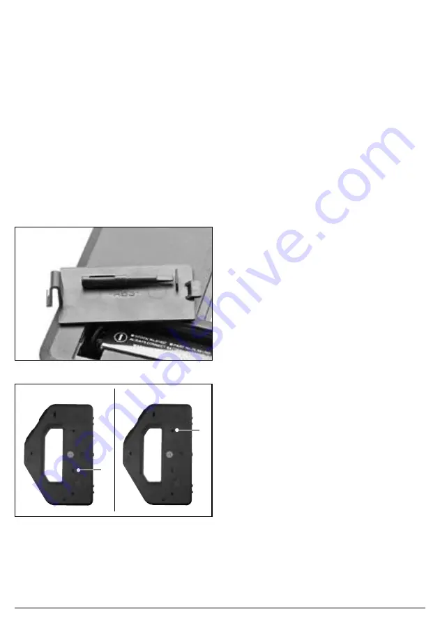
A small screwdriver (15) is supplied for device adjustment and is located
on the back of the battery compartment cover (10) (Fig. 5).


