8
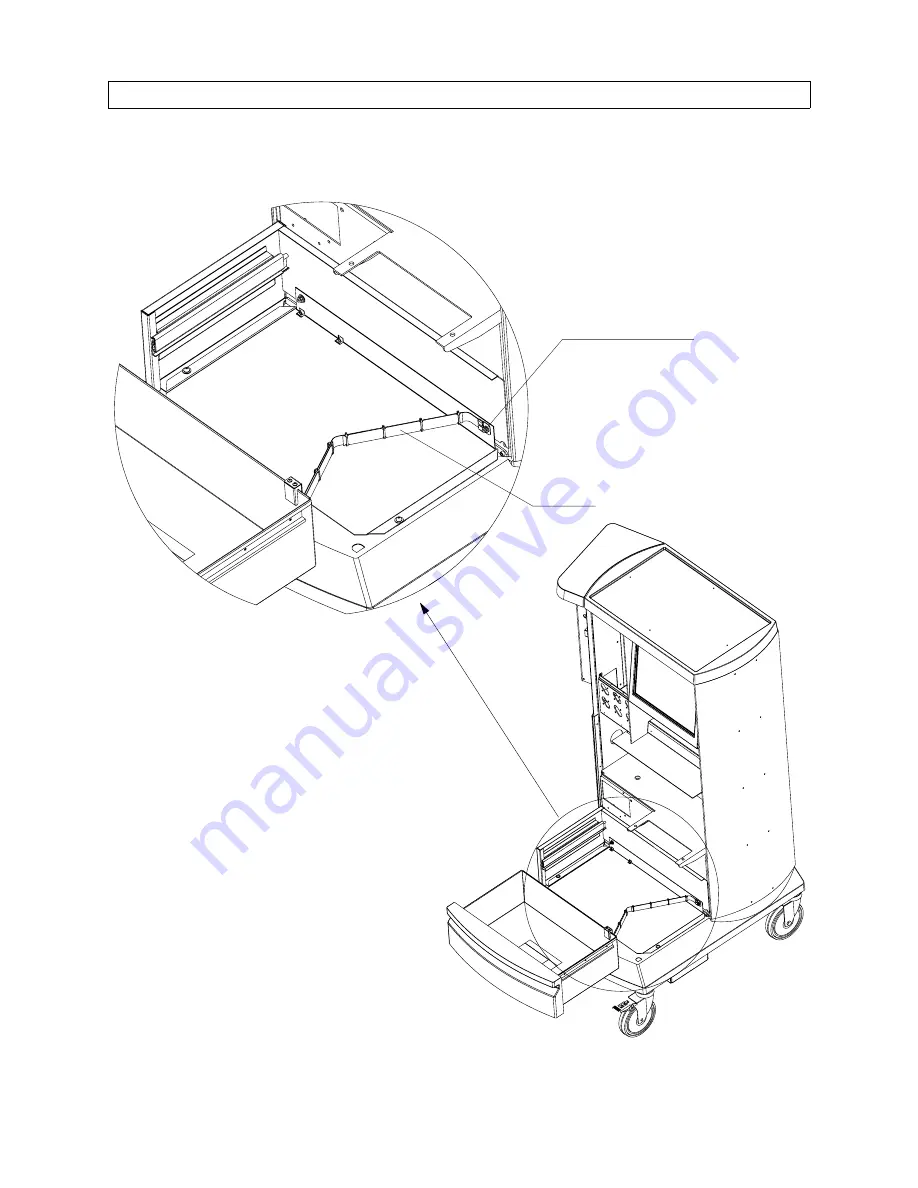
FIGURE 6. Ground Strap Installation
SP24406
GROUND STRAP ASSEMBLY
10-32 KEP NUT
Installation Procedure (continued)
RETURN TO CD-ROM TABLE OF CONTENTS
RETURN TO SERVICE PROCEDURE TABLE OF CONTENTS
Страница 1: ...ce Procedure Field Date 28 March 2003 2003 Draeger Medical Inc Part Number SP00244 Rev B NM6000 Auxiliary Video Installation RETURN TO CD ROM TABLE OF CONTENTS RETURN TO SERVICE PROCEDURE TABLE OF CON...
Страница 2: ...RETURN TO CD ROM TABLE OF CONTENTS RETURN TO SERVICE PROCEDURE TABLE OF CONTENTS...
Страница 3: ...1 4 Pull all circuit breakers to their out position 1 5 Remove and discard the upper rear cover from the machine 1 6 Remove the table lamp panel with strip chart recorder if machine is so equipped at...
Страница 4: ...G VIDEO CABLE EXISTING POWER CABLE VIDEO SPLITTER POWER CABLE 4 40 X 3 8 IN BTN HD SCREW LOCK WASHER 4X AUX VIDEO POWER PCB NEW VIDEO CABLE 3X NEW VIDEO CABLE NEW VIDEO SPLITTER 6 32 KEP NUT 4X REMOTE...
Страница 5: ...n in Figure 1 1 18 Connect the three remote video cables 4117783 to Ports C D and E on the video splitter Coil the excess length on each cable and tie wrap as shown in Figure 1 1 19 Apply the new labe...
Страница 6: ...d display option at this time 1 24 Install the new cover 4117794 on the rear of the machine SP24402a THREADED SPACER 2X PER CONNECTOR VIDEO 1 VIDEO 2 VIDEO 3 NEW REAR COVER NEW REAR COVER IF NARKOMED...
Страница 7: ...of the machine project through the holes in the drawer housing and battery shield Secure the left rear corner of the shield and housing with a 10 32 Kep nut and 10 flat washer Secure the front of the...
Страница 8: ...stud projecting through the battery shield and secure it with a 10 32 Kep nut See Figure 6 2 9 Attach the other end of the ground strap assembly to the ground strap bracket as shown in Figure 5 Secur...
Страница 9: ...he machine s self diagnostics flat panel display remote display aux lamp and strip chart recorder if fitted are working properly 2 15 Perform electrical safety and battery tests refer to Section 6 in...
Страница 10: ...8 FIGURE 6 Ground Strap Installation SP24406 GROUND STRAP ASSEMBLY 10 32 KEP NUT Installation Procedure continued RETURN TO CD ROM TABLE OF CONTENTS RETURN TO SERVICE PROCEDURE TABLE OF CONTENTS...
Страница 11: ...Figure 7 to the transformer mounting plate with four 10 32 Kep nuts 3 7 Reinstall the IPM pod if applicable 3 8 Install the new cover on the rear of the machine 3 9 Apply the new label 4117780 on the...
Страница 12: ...s flat panel display remote display aux lamp strip chart recorder and IPM if fitted are working properly 3 17 Perform electrical safety and battery tests refer to Section 6 in the Narkomed 6000 Techni...
Страница 13: ...MOUNTING PLATE 10 32 KEP NUT 4X 12 IN GCX RAIL GCX COUNTER TOP ARM GCX TOP SHELF CHANNEL BASE PLATE DISPLAY UNIT DISPLAY POWER CORD VIDEO CABLE AUXILIARY OUTLET STRIP MOUNTING CLIP RELOCATION DUST CAP...
Страница 14: ...le from the display unit to the Video 1 Video 2 or Video 3 connector on the back of the machine as shown in Figure 8 4 6 Verify there is a dust cap 4117861 on each of the unused video connectors 4 7 C...
Страница 15: ...form electrical safety and battery tests refer to Section 6 in the Narkomed 6000 Technical Service Manual 4 13 Locate the Operator s Manual binder assembly and insert Supplement 4117816 Auxiliary Vide...
Страница 16: ...ISOLATION TRANSFORMER GCX TRANSFORMER MOUNTING PLATE 10 32 KEP NUT 4X 19 IN GCX RAIL GCX PIVOT ARM DISPLAY UNIT DISPLAY POWER CORD VIDEO CABLE DUST CAP Installation Procedure continued RETURN TO CD RO...
Страница 17: ...RETURN TO CD ROM TABLE OF CONTENTS RETURN TO SERVICE PROCEDURE TABLE OF CONTENTS...
Страница 18: ...raeger Medical Inc 3122 Commerce Drive Telford PA 18969 Tel 215 721 5402 800 543 5047 Fax 215 721 5784 Web www draegermedical com Printed in the U S A RETURN TO CD ROM TABLE OF CONTENTS RETURN TO SERV...