June 14, 2002
UM026.14100
www.dpstele.com
(800)622-3314
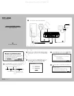
Rear Panel Connections
10BaseT
LAN Connection
Primary
Interface
(Male DB9)
Configuration
Interface
(Female DB9)
Power
Block
Power Connection (Main KDA Shelf Only)
1. Remove the fuse from the front panel and turn off the power supply when connecting the power from the main feed.
2. Connect a -48VDC line to the -BATT terminal and the ground to the GND terminal.
3. Turn on main power with the fuse still removed.
4. Connect the black common lead of a volt meter to ground and the red lead to -BATT. The Meter should read the battery
level (-43 to -53VDC). If not, check your power supply
5. Do not re-insert the fuse (powering up the unit) until all other connections have been made.
Note:
Observe polarity when connecting battery leads. If using the -48VDC red/black cables supplied with the unit, connect black to
GND and red to -BATT. Standard gauge is 20AWG, which varies from 18-24AWG.
5 4 3 2 1
9 8 7 6
DSR
GND
RX
TX
RTS
CTS
Female
PIN# Signal Description
1
2
3
4
5
6
7
8
9
NC
TX
RX
DSR
GND
NC
CTS
RTS
NC
Not connected
Transmit data
Receive data
Data set ready
Ground
Not connected
Clear to send
Request to send
Not connected
1 2 3 4 5
6 7 8 9
DSR
GND
RX
TX
RTS
CTS
Male
PIN# Signal Description
1
2
3
4
5
6
7
8
9
GND
DSR
RX
TX
NC
NC
RTS
CTS
NC
Ground
Data set ready
Receive data
Transmit data
Not connected
Not connected
Request to send
Clear to send
Not connected
NIA LED Display
Tbl. 1 - NIA LED Descriptions.
LED
Condition
Description
TST
ALM
STX
SRX
CMD
MSG
LTX
LRX
Flash GN
RD
GN
RD
Flash RD/GN
Flash GN
Flash RD
Flash GN
Flash RD
Flash GN
Flash GN
Flash RD
Unit operating normally
MOD switch pressed
No standing alarms
Standing alarms exist
Unreported COS alarms exist
Serial port transmitting
Serial port receiving
SNMP Get/GetNext
SNMP Set
Trap
LAN port transmitting
LAN port receiving