


DV425TR DIRECT VENT ROOM HEATER
02/01 Page 41 250-5533
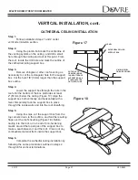
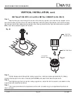
Step 3.
Secure the flashing (SDV #705C) to the top of
the masonry chimney using a bead of non-hardening
sealant-adhesive. If the flashing is larger than the top
of the chimney, cut and fold flashing as needed to fit
chimney (Figure 23).
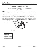
Step 4.
To determine the length of flex needed,
measure from 3” (76mm) above the top of the flashing
down to the level of the opening. Add the distance
from the center of the chimney out through the
wall. Cut a piece of 4” (102mm) flex to this
length (extended to its nominal length). Be sure to
leave 2”-3” (51mm-76mm) of flex above the existing
chimney to allow for connection to the termination kit.
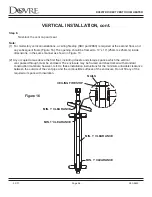
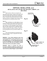
Step 5.
Connect the flex liner to the top adapter using three (3) sheet metal screws (see Figure 19, page 44).
Step 6.
Feed the flex liner through the flashing into the chimney. Carefully feed the flex liner down the chimney
to the bottom and out the opening in the masonry wall, forming an angle to line up the flex liner with the
vent opening on the appliance.
WARNING: Do not let the flex liner sag below the level at which it will connect to the appliance or
connector. This could allow hot gas to become trapped and potentially become a fire hazard. The flex
liner path should always be sloped up toward the termination cap.
INSTALLATION INTO AN EXISTING MASONRY CHIMNEY, cont.
(USA ONLY)
VERTICAL INSTALLATION, cont.
Fig. 23
CUT AND BEND FLASHING AS
NEEDED TO FIT CHIMNEY
SEALANT-ADHESIVE


