Dover Environmental Solutions BAYNE TL 1128 Скачать руководство пользователя страница 18

TL 1128 (TOP HOLES)

Issued August 2016

Revision No: 006

Printed in U.S.A.

Copyright 2016, Bayne Premium Lift Systems

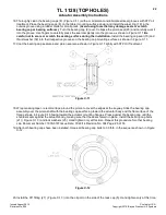
Diverter Valve Information

14

OPERATION AND INSTALLATION INFORMATION

WI-0026
The Bayne diverter valve establishes priority flow to the lifter circuit “P1” and “P2” ports and bypasses oil to the “OUT” port,

which typically supplies flow to the remainder of the truck’s hydraulic circuit. This bypass occurs only after the lifter circuit is

satisfied. The priority flow is controlled by the flow regulator cartridge (FR1) (and FR2 in dual applications) in combination

with the differential pressure sensing valve (DPS). This allows the valve to maintain constant flow regardless of changes in

load pressure or volume flow rate. Since both the lifter circuit and bypass flow can be utilized in the operation of the truck

regardless of which pressure is greater, a single pump can be used to supply two circuits or operations.
The lifter circuit flow is regulated and maintained by the flow regulator cartridge (FR1) (and FR2 in dual applications). The

differential pressure sensing valve (DPS), rated for 75 gpm of flow and 3000 psi of pressure, is operated by an internal

spring and dampening orifice (OR) which establishes a pressure drop across the block sufficient to ensure the correct

operation of the flow regulator (FR1). For a dual diverter valve, a second flow regulator cartridge (FR2) is installed in the

“FR2” cavity and a shuttle valve (DSV) is installed in place of the SAE plug in the “DSV” cavity. Once the pressure drop is

established, a precision metered flow is provided to the tipper circuit(s) with additional flow being bypassed to the “OUT”

port.
The operation of the diverter valve does not require the use of a tank line to be run to the “T” port. However, the efficiency

of the block will be significantly increased if a tank line is installed. The logic circuit of the block will manage the flow of oil

returning from the tipper circuit to ensure optimum performance. This is primarily controlled with the sequence valve (PSV)

which is factory set and should not be adjusted. All oil returning from the tipper circuit will normally be regenerated into the

outgoing flow to ensure that the downstream functions are not slowed in any way. When the downstream backpressure

rises to a predetermined pressure, the block will redirect the flow to the “T” port to increase the overall efficiency of the

block and reduce the pressure drop through the block. If the “T” port is connected to a tank line, the oil will be dumped

through the block at a lower pressure. This allows downstream functions to operate at the highest possible pressure when

pressure is being required. If the “T” port is blocked, the oil will be redirected back into the outgoing flow through the check

valve (CV).
A relief circuit for the tipper function is controlled by a relief valve (RV), which is preset to 2300 psi. This can be adjusted to

limit pressure to the tipper(s). This relief valve is more efficient than the relief in the hand valve and will operate with less

noise. It is recommended that it be adjusted to relieve before the hand valve relief. It may also be used to limit the weight

the lifter can dump. This may be beneficial in avoiding damage to cans resulting from overloading. This should be the only

adjustment that the block may require. Any other adjustments should only be made after close consultation with Bayne’s

Engineering Department to ensure proper operation.

Содержание Environmental Solutions BAYNE TL 1128

Страница 1: ... CUSTOMER NAME ____________________ SERIAL NUMBER ____________________ 1900 0187 Revision No 006 LICENSED UNDER ONE OR MORE OF THE FOLLOWING U S AND CANADIAN PATENTS 5 503 512 4 773 812 1 327 765 5 447 405 1 335 648 5 308 211 5 333 984 5 826 485 2020 Bayne Premium Lift Systems ...

Страница 2: ...e the use of tools or blocking devices specially designed for the purpose Special tools should be used when and as recommended It is important to note that some warnings against the use of specific methods that can damage the product or render it unsafe are stated in the service manual It is also important to understand these warnings are not exhaustive Bayne THINLINE could not possibly know evalu...

Страница 3: ...Assembly Drawings and Part Numbers 31 1900 0187 TL 1128 Top Holes Lifter Assembly 35 7603 1501 Hook Bearing Mount Assembly 36 2000 1230 Torque Bearing Assembly 37 2000 1338 Lower Idler Bearing Assembly 38 2000 1335 Upper Idler Bearing Assembly 39 H3000027 TL Series Specifications 43 6900 0700 Hydraulic Schematic 44 6900 0704 Hydraulic Schematic 45 M3500005 Diverter Valve Parts 46 8000 0780 Diverte...

Страница 4: ...INTENTIONALLY LEFT BLANK TL 1128 TOP HOLES ...

Страница 5: ...TL 1128 TOP HOLES Issued August 2016 Revision No 006 Printed in U S A Copyright 2016 Bayne Premium Lift Systems 1 TL 1128 TOP HOLES PART NUMBER 1900 0187 REVISION NO 006 OPERATION AND PARTS MANUAL ...

Страница 6: ...perate or maintain this equipment Additional copies may be obtained from your local dealer or directly from Bayne THINLINE Premium Lift Systems B Lockout Tagout Procedures All applicable OSHA lockout tagout regulations must be followed when working on this equipment Failure to comply with these procedures can result in serious injury or death C Safety Decals Safety decals attached to your Bayne TH...

Страница 7: ...f large commercial containers without interference D The faceplate is normally at 45 degrees in the dump position and extends 13 to 15 from the back of the mainframe into the hopper or container opening This places the cart or barrel 16 to 18 into the truck or container opening thus reducing any potential spillage of materials E Cycle times for safe fast efficient service 6 8 seconds for rear load...

Страница 8: ...t Bayne Machine Works Inc for fast response to customer request J Two 2 year limited warranty from date of delivery on all units and models when properly maintained and operated within the recommended cycle time NOTICE All lift units and parts are inspected by our Quality Control Department before shipment to insure that you always receive the highest quality available in the lift business For mor...

Страница 9: ...r more detailed information A Mounting lifter s on the truck 1 The truck should be emptied and cleaned before any installation The truck should be parked on a level solid surface a concrete floor if possible 2 All lights tags steps etc that will interfere with the installation should be removed and or relocated 3 Position the lifter s on the sill of the truck per Figure A 1 and mounting height dra...

Страница 10: ... assembly s on the mounting bracket s Figure A 2 C Mounting diverter valve on the truck 1 Choose and mark an acceptable location to mount the diverter valve assembly This location should be near the truck s main hydraulic pressure and tank lines on the same area of the truck where the lifter is mounted 2 Weld diverter valve mounting bracket to the truck 3 After the weld has cooled paint the mounti...

Страница 11: ...attempting any hydraulic connections turn the truck s engine off and release all hydraulic pressure from the system Refer to the hydraulic layouts Figure A 3 and hydraulic schematics while performing the following steps See Appendix A for drawings NOTICE Always clean lubricate fitting threads before installation Single Lifter Installation Dual Lifter Installation Figure A 3 30 ...

Страница 12: ... s 7 Disassemble each hose clamp assembly and position weld plates where needed and weld in place 8 After the weld has cooled paint the weld plates to match the truck color 9 After the paint has dried reassemble the hose clamp assemblies around the hoses E Adjusting relief valve settings The diverter valve 1 Figure A 4 supplies the cart lifter hydraulic system with approximately 2 GPM of oil flow ...

Страница 13: ... off and release all hydraulic pressure from the system 7 Install the 3000 psi hydraulic pressure gauge with the necessary adapter in the hydraulic line connected to the IN port of the hand valve as shown in Figure A 5 If installing dual lifters install the hydraulic gauge at either one of the hand valves Figure A 5 8 Start the truck s engine and engage the hydraulic system 9 Setting the diverter ...

Страница 14: ...ted to the IN port of the hand valve f For dual lifters install the hydraulic pressure gauge in the IN port of the other hand valve as shown in Figure A 5 start the truck s engine engage the hydraulic system and repeat step 10 11 Reinstall the cap nut s 6 Figure A 4 on the hand valve relief valve s 5 to secure the correct pressure setting s 12 Tighten the lock nut 4 Figure A 4 on the lifter circui...

Страница 15: ... be dumped is placed on the lifter 2 ACTUATOR DUMP The rotary actuator cycles to dump the contents of the cart into the box During this cycle the lower hooks automatically rotate to lock the cart to the lifter 3 ACTUATOR REVERSE The rotary actuator reverses its cycle returning the cart to the start position The lower hooks automatically retract to unlock the cart from the lifter Figure B 1 WARNING...

Страница 16: ...he cycle persons enter this area the operator most stop all motion of the lifter until the area is cleared Dump Zone To prevent serious injury or death operators and bystanders should remain outside the Dump Zone Figure B 2 at all times If it becomes necessary to enter this area all applicable OSHA lockout tagout regulations must be followed Operator Area To provide a clear unobstructed view of bo...

Страница 17: ...ing of the cart to the lifter To adjust the setting loosen the jam nuts 1 on the spherical rod ends 2 Remove the bolts 3 that hold the rod ends to the lower hooks 4 Screw the rod ends in or out as required to obtain the correct dimension at A Replace the bolts 3 and tighten the jam nuts 1 Figure B 3 CAUTION The distance in Figure B 3 is an arbitrary figure based on information furnished by cart ma...

Страница 18: ...g bypassed to the OUT port The operation of the diverter valve does not require the use of a tank line to be run to the T port However the efficiency of the block will be significantly increased if a tank line is installed The logic circuit of the block will manage the flow of oil returning from the tipper circuit to ensure optimum performance This is primarily controlled with the sequence valve P...

Страница 19: ...ockage occurs because of the differential pressure sensing valve needing 80 psi to initially open and allow the flow regulators function The path of the lubrication oil is therefore stopped because the valve does not open When the oil is blocked the pump will rotate and cavitate in the lubricating oil causing heat to build up over an extended period of time possibly leading to premature pump failu...

Страница 20: ...THINLINE Lift System comes clean from the factory If removed be sure the hoses cylinder and fittings are clean before re installing them on the unit Inspect your cart lifter on a weekly basis for loose bolts fittings oil leaks etc Tighten loose hardware as necessary and replace necessary seals to repair oil leaks In order to maintain warranty and for preventive maintenance grease all points weekly...

Страница 21: ... torque values given apply to clean dry threads only Follow these directions closely when repairing the Rotary Actuator 1 Install the piston seal load ring 13 Figure C 1 in the small groove on the head of the actuator rack 2 Place the square piston seal 17 over the load ring 13 in the same small groove a small blunt flathead screwdriver may be used taking care not to scratch or damage the seal Ins...

Страница 22: ...the inner races 10 on the pinion shaft radius end first as shown in Figure C 3 until the races seat against the gear teeth After the races seat against the gear teeth twist the races on the pinion 360º to spread the retaining compound evenly Wipe off any excess retaining compound Figure C 3 4 Place the actuator body 7 Figure C 4 on the edge of the table mounting flanges closest to the assembler wi...

Страница 23: ...n the body Simultaneously slide the racks into the bores so that the racks mesh with the pinion in the same position Rotate the pinion shaft to engage the racks into the pinion Figure C 5 6 Check the position of the racks in the pinion by making sure both racks seat against the actuator body at the same time and also when the racks are seated against the body the key ways on the pinion shaft shoul...

Страница 24: ...short threaded end into the actuator body Hand tighten only at this time the torque needed will be applied later in the procedure 9 Place the tube cap 4 Figure C 13 on the table Coat the sides of the two bores in the tube cap with STP Oil Treatment Install the cap over the tubes and rod studs with the oil port positioned to the left as shown in Figure C 13 Using a rubber mallet tap the tube cap ov...

Страница 25: ...be cap as shown in Figure C 13 Attach the rack cap to the actuator body using the socket head bolts 22 Figure C 13 and lock washers 26 Torque the bolts to 90 ft lb in the sequence shown in Figure C 10 Figure C 10 14 Reposition the actuator so that the pinion shaft can be rotated with no obstacles Rotate the pinion shaft to ensure that the racks move freely Also make sure that the key ways point pe...

Страница 26: ...g cap mounting surface as shown in Figure C 11 17 Coat the bearing cap seal area and pinion seal area shown in Figure C 11 lightly with STP Oil Treatment Figure C 11 18 Wrap masking tape or electrical tape around the pinion to cover the edges at the keyway Slide the bearing cap assembly over the pinion shaft with the bearing cap seal facing toward the actuator body and the flat surface of the flan...

Страница 27: ...2 Install the rack cap extension tube assembly 29 Figure C 13 between the 90 fitting in the rack cap and the 45 fitting in the tube mounting bracket as shown in Figure C 13 Tighten all connections 23 Install the orifice plug 11 Figure C 13 into the oil port on the side of the tube cap 4 and install the 90 fitting 27 into the oil port over the orifice plug as shown in Figure C 13 Turn the fitting s...

Страница 28: ...TL 1128 TOP HOLES Issued August 2016 Revision No 006 Printed in U S A Copyright 2016 Bayne Premium Lift Systems Actuator Assembly Instructions 24 ACTUATOR ASSEMBLY Figure C 13 ...

Страница 29: ...the Actuator assembly and is assembled into the rack cap Before starting the assembly of the Slowdown refer to the exploded parts drawing and parts list Figure D 4 found at the end of these instructions to familiarize yourself with the individual components Prepare a clean surface in an area free from blowing dust and contaminants in which to assemble the Slowdown Be sure that all parts are clean ...

Страница 30: ... on the o ring plug 9 with STP Oil Treatment Screw the o ring plug 9 into the plunger housing 1 on top of the spring 4 and tighten to 30 in lb torque Figure D 2 3 Coat the o rings on the plunger housing 1 Figure D 3 and the o ring on the o ring plug 8 with STP Oil Treatment Screw the plunger housing 1 into the top of the rack cap 3 Figure D 4 and torque to 30 in lb Screw the o ring plug 8 into the...

Страница 31: ...TL 1128 TOP HOLES Issued August 2016 Revision No 006 Printed in U S A Copyright 2016 Bayne Premium Lift Systems Actuator Assembly Instructions 27 Figure D 4 ...

Страница 32: ...ic components down stream of diverter valve not operating or operating extremely slow 1 Truck system hydraulic pressure too low 1 Check and adjust pressure on truck system relief and full system relief in diverter valve 2 Faulty full system relief valve cartridge in diverter valve 2 Replace full system relief valve cartridge in diverter valve 3 Faulty truck system relief valve 3 Consult truck main...

Страница 33: ...e not standard spread dimensions 2 Re adjust saddle to hook dimension for these carts Lifter looses cart when dumping 1 Saddle to hook dimension out of adjustment 1 Adjust saddle to hook dimension as described in the Operation Instructions of this manual 2 Lift bars on cart are bent or spread apart 2 Replace cart or install new bars Lift bars on cart are being spread apart or damaged 1 Saddle to h...

Страница 34: ... 1128 TOP HOLES Issued August 2016 Revision No 006 Printed in U S A Copyright 2016 Bayne Premium Lift Systems Appendix A Assembly Drawings and Part Numbers 30 APPENDIX A ASSEMBLY DRAWINGS AND PART NUMBERS ...

Страница 35: ...TL 1128 TOP HOLES Issued August 2016 Revision No 006 Printed in U S A Copyright 2016 Bayne Premium Lift Systems Appendix A Assembly Drawings and Part Numbers 31 ...

Страница 36: ...TL 1128 TOP HOLES Issued August 2016 Revision No 006 Printed in U S A Copyright 2016 Bayne Premium Lift Systems Appendix A Assembly Drawings and Part Numbers 32 ...

Страница 37: ...TL 1128 TOP HOLES Issued August 2016 Revision No 006 Printed in U S A Copyright 2016 Bayne Premium Lift Systems Appendix A Assembly Drawings and Part Numbers 33 ...

Страница 38: ...TL 1128 TOP HOLES Issued August 2016 Revision No 006 Printed in U S A Copyright 2016 Bayne Premium Lift Systems Appendix A Assembly Drawings and Part Numbers 34 ...

Страница 39: ...TL 1128 TOP HOLES Issued August 2016 Revision No 006 Printed in U S A Copyright 2016 Bayne Premium Lift Systems Appendix A Assembly Drawings and Part Numbers 35 ...

Страница 40: ...TL 1128 TOP HOLES Issued August 2016 Revision No 006 Printed in U S A Copyright 2016 Bayne Premium Lift Systems Appendix A Assembly Drawings and Part Numbers 36 ...

Страница 41: ...TL 1128 TOP HOLES Issued August 2016 Revision No 006 Printed in U S A Copyright 2016 Bayne Premium Lift Systems Appendix A Assembly Drawings and Part Numbers 37 ...

Страница 42: ...TL 1128 TOP HOLES Issued August 2016 Revision No 006 Printed in U S A Copyright 2016 Bayne Premium Lift Systems Appendix A Assembly Drawings and Part Numbers 38 ...

Страница 43: ...TL 1128 TOP HOLES Issued August 2016 Revision No 006 Printed in U S A Copyright 2016 Bayne Premium Lift Systems Appendix A Assembly Drawings and Part Numbers 39 ...

Страница 44: ...TL 1128 TOP HOLES Issued August 2016 Revision No 006 Printed in U S A Copyright 2016 Bayne Premium Lift Systems Appendix A Assembly Drawings and Part Numbers 40 ...

Страница 45: ...TL 1128 TOP HOLES Issued August 2016 Revision No 006 Printed in U S A Copyright 2016 Bayne Premium Lift Systems Appendix A Assembly Drawings and Part Numbers 41 ...

Страница 46: ...TL 1128 TOP HOLES Issued August 2016 Revision No 006 Printed in U S A Copyright 2016 Bayne Premium Lift Systems Appendix A Assembly Drawings and Part Numbers 42 ...

Страница 47: ...TL 1128 TOP HOLES Issued August 2016 Revision No 006 Printed in U S A Copyright 2016 Bayne Premium Lift Systems Appendix A Assembly Drawings and Part Numbers 43 ...

Страница 48: ...TL 1128 TOP HOLES Issued August 2016 Revision No 006 Printed in U S A Copyright 2016 Bayne Premium Lift Systems Appendix A Assembly Drawings and Part Numbers 44 ...

Страница 49: ...TL 1128 TOP HOLES Issued August 2016 Revision No 006 Printed in U S A Copyright 2016 Bayne Premium Lift Systems Appendix A Assembly Drawings and Part Numbers 45 ...

Страница 50: ...TL 1128 TOP HOLES Issued August 2016 Revision No 006 Printed in U S A Copyright 2016 Bayne Premium Lift Systems Appendix A Assembly Drawings and Part Numbers 46 ...

Страница 51: ...TL 1128 TOP HOLES Issued August 2016 Revision No 006 Printed in U S A Copyright 2016 Bayne Premium Lift Systems Appendix A Assembly Drawings and Part Numbers 47 ...

Страница 52: ...TL 1128 TOP HOLES Issued August 2016 Revision No 006 Printed in U S A Copyright 2016 Bayne Premium Lift Systems Appendix A Assembly Drawings and Part Numbers 48 ...

Страница 53: ...TL 1128 TOP HOLES Issued August 2016 Revision No 006 Printed in U S A Copyright 2016 Bayne Premium Lift Systems Appendix A Assembly Drawings and Part Numbers 49 ...

Страница 54: ...INTENTIONALLY LEFT BLANK 50 TL 1128 TOP HOLES ...

Страница 55: ...tion operation and installation information 14 possible problems 14 F final operation and mounting 5 I installation instructions 5 instructions actuator assembly 17 slowdown assembly 17 L lower hook adjustment 11 M maintenance instructions 16 making hydraulic connections 5 mounting 5 O operation instructions 11 S safety 2 safety zones 11 specifications 3 T troubleshooting chart 28 ...

Страница 56: ...www baynethinline com Customer Care 800 535 2671 Bayne Premium Lift Systems 4301 Gault Avenue North Fort Payne AL 35967 ...

Отзывы: