


Lit. No. 72936, Rev. 01
6
October 15, 2019
SAFETY
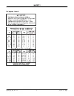
TORQUE CHART
1/4-20
109
154
1/4-28
121
171
5/16-18
150
212
5/16-24
170
240
3/8-16
269
376
3/8-24
297
420
7/16-14
429
606
7/16-20
9/16-12
9/16-18
5/8-11
5/8-18
3/4-10
3/4-16
7/8-9
7/8-14
474
669
644
909
1-8
1-12
704
995
1/2-13
1/2-20
11.9
13.7
24.6
27.3
43.6
26.9
53.3
93
148
49.4
69.8
77.9
106.4
120.0
8.4
9.7
17.4
19.2
30.8
35.0
49.4
55.2
75.3
85.0
M6 x 1.00
M12 x 1.75
M8 x 1.25
M14 x 2.00
M10 x 1.50
M27 x 3.00
M22 x 2.50
M30 x 3.50
M24 x 3.00
M20 x 2.50
11.1
19.5
38.5
67
107
7.7
613
778
1139
1545
450
428
562
796
1117
M33 x 3.50
M36 x 4.00
2101
2701
1468
1952
325
M16 x 2.00
231
167
M18 x 2.50
318
222
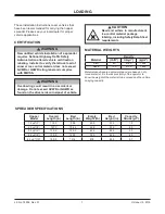
Recommended Fastener Torque Chart
Size
Size
Torque (ft-lb)
Grade
5
Grade
8
Metric Fasteners Class 8.8 and 10.9
These torque values apply to fasteners
except those noted in the instructions.
Torque (ft-lb)
Grade
5
Grade
8
Size
Size
Torque (ft-lb)
Class
8.8
Class
10.9
Torque (ft-lb)
Class
8.8
Class
10.9
Inch Fasteners Grade 5 and Grade 8
CAUTION
Read instructions before assembling.
Fasteners should be
fi
nger tight until instructed
to tighten according to the Torque Chart.
Use standard methods and practices when
attaching spreader, including proper personal
protective safety equipment.