35
ED50
08-2018
DL4614-140
dormakaba ED50 OHC Installation Instructions
Chapter 16
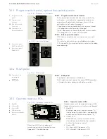
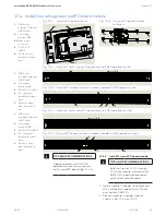
16.4 Program switch panel jamb cutout
16.4.1 Program switch panel cutout and
mounting holes.
1. Cutout jamb, drill mounting holes for
program switch panel.
Reference Para. 14.3 for cutout detail.
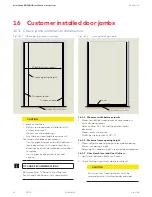
CAUTION
Mounting holes for program
switch panel flat head screws
depend on jamb material.
Metal jambs: tap drill for 18-8
screw supplied with panel.
Wood jambs: Select fastener.
16.5 RJ45 panel jamb cutout, double doors
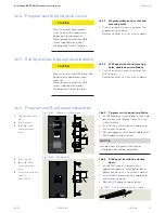
16.6 Program and RJ45 panel installation
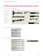
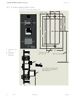
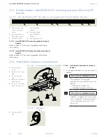
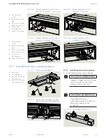
Fig. 16.6.1 Program switch panel
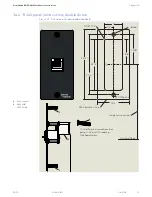
Fig. 16.6.2 RJ45 panel
1
Program switch panel
cable
2
RJ45 connector
3
18-8 x 5/8" SS FH
undercut machine
screw
16.6.1 Program switch panel installation
1. Install program switch panel in lock side
jamb cutout. Reference Para. 14.3 for
cutout details.
2. Insert RJ45 communication cable plug
into socket on panel.
3. Route program switch panel cable and
RJ45 cable to top of jamb.
NOTICE
Double doors: Program switch panel
installed on active door side jamb.
2
3
1
3
4
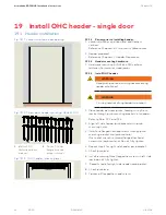
16.6.2 RJ45 panel installation, double
doors.
1. Install RJ45 panel in jamb cutout
opposite program switch panel jamb.
Reference Para. 14.4 for cutout details.
2. Insert RJ45 communication cable plug
into socket on panel.
3. Route RJ45 cable to top of jamb.
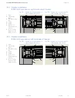
Fig. 16.3.3 RJ45 communication cable
2
RJ45 connector
3
18-8 x 5/8" SS FH
undercut machine
screw
4
RJ45 communication
cable, 10'
DX4607-020
2
3
3
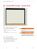
16.5.1 RJ45 panel cutout and mounting
holes, double door installations.
1. Cutout jamb, drill mounting holes for
RJ45 panel.
Reference Para. 14.4 for cutout detail.
CAUTION
Mounting holes for RJ45 panel flat
head screws depend on jamb
material.
Metal jambs: tap drill for 18-8
screw supplied with panel.
Wood jambs: Select fastener.

