(P/N) 762.128 Rev G 05/17 • © copyright 2009-2018
2
dormakaba
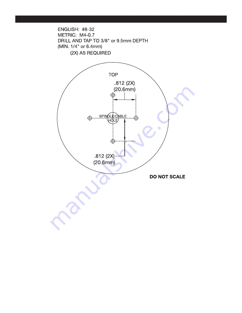
DIAL RING/FRONT HOUSING BASE MOUNTING TEMPLATE
Страница 1: ...Installation Guide Electronic Entry Device LA GARD Basic Gard Series Document Number 762 128 Rev G 05 2018 ...
Страница 2: ...lt ALKALINE batteries only The use of a high quality name brand battery Energizer or Duracell is recommended BASIC TOOLS AND MATERIALS REQUIRED Medium Phillips head screwdriver 2 recommend magnetized tip Small flat file or deburring stone Tape measure or ruler ESD wrist band PREPARATION FOR NEW INSTALLATION IF REQUIRED 1 Use the template provided to establish the exact locations relative to the sp...
Страница 3: ... P N 762 128 Rev G 05 17 copyright 2009 2018 2 dormakaba DIAL RING FRONT HOUSING BASE MOUNTING TEMPLATE ...
Страница 4: ...n the keypad over the mounting screws and slide the keypad housing down Ensure there are no wires or cables trapped between the Entry Device and the safe door 3035 AND 3125 ROUND ENTRY DEVICES NOTE The 3125 entry is not UL listed SWING BOLT 1 Mount the dial plate p n 2676 centered on the through hole Attach the dial plate with the two mounting screws US 8 32 US or the M4 0 7 metric and the shoulde...
Страница 5: ...f safe door Route the cable through the groove of the cable protector 11 0 Gently pull on the cable to assure that there is no excess cable in the spindle hole that would rub on the metal door 12 0 Install the lock with the bolt extended onto the spindle INSTALLING BATTERIES The 3035 3125 Entry Device require either a battery box 2788 or 4001 or a battery alarm box 2789 or 4002 to provide power to...
Страница 6: ...3 and blocking pins p n 2894 into the holes located on the back of the keypad Figure 7 5 Skip this step if the battery door is to be removable Otherwise attach the battery door to the keypad by first inserting the hinge pin into the hole on the battery door and then insert the battery door with hinge pin into the hinge pin hole on the keypad housing adjacent to the locking pin hole See Figure 7 WA...
Страница 7: ...ve spindle and cut as marked in Step 7 10 Reassemble keypad spindle and bearing plate 11 Skip this step if the battery door is to be removable Otherwise attach the battery door to the keypad by first inserting the hinge pin into the hole on the battery door and then insert the battery door with hinge pin into the hinge pin hole on the keypad housing adjacent to the locking pin hole Figure 7 DO NOT...
Страница 8: ...r was installed without the hinge pin it will detach from the Entry Device when it is opened 2 Allow the battery connector and its attached leads to drop down and out of the battery compartment If it does not drop gently pull on the battery connector until it does CAUTION Hold on to battery terminal connector to avoid pulling the wires out of housing 3 Connect a new 9 Volt alkaline battery to the ...
Страница 9: ...f the knob 2 Cut the spindle to a length of 820 20 8mm plus the door thickness Figure NOTE the spindle must be deburred 3 Install the knob assembly using the two 8 32 x 5 16 phillips pan screws 4 Install the lock with the bolt extended onto the spindle placing it flush to the mounting surface Refer to lock installation instructions which are available at www kaba mas com Figure 14 DOOR MOUNTING PL...