9. Insert the power key into its receptacle.
10. Set the power switch to ON.
11. Connect the
USB-A/USB-B cable
between the
⋆
LISER
TM
& LED/LD Light Source
and the computer.
12. Install the
on the computer. Double-click on the DoricNeuroscienceStudioSetup_vX.X.exe
file located on the Doric USB memory stick supplied with the
⋆
LISER
TM
& LED/LD Light Source
and follow the
on-screen instructions (help is also available in the
Doric Neuroscience Studio User Manual
, which can be
downloaded on our
, section
SUPPORT
).
13. If needed, connect an external device to the
⋆
LISER
TM
& LED/LD Light Source
by using one of the input BNC
port. In this configuration, the driver will wait the signal from another device, consequently the light source will
be triggered. To follow an external device, select the external TTL or the external analog mode for the desired
channel (see section
14. If needed, connect a data acquisition system or an external device to the
⋆
LISER
TM
& LED/LD Light Source
by using
the output BNC port of the desired channel. A data acquisition system enables the viewing and the recording
of the signal generated by an external device connected to the light source. The output BNC can also be used
to connect an external device that will be triggered by the light source.
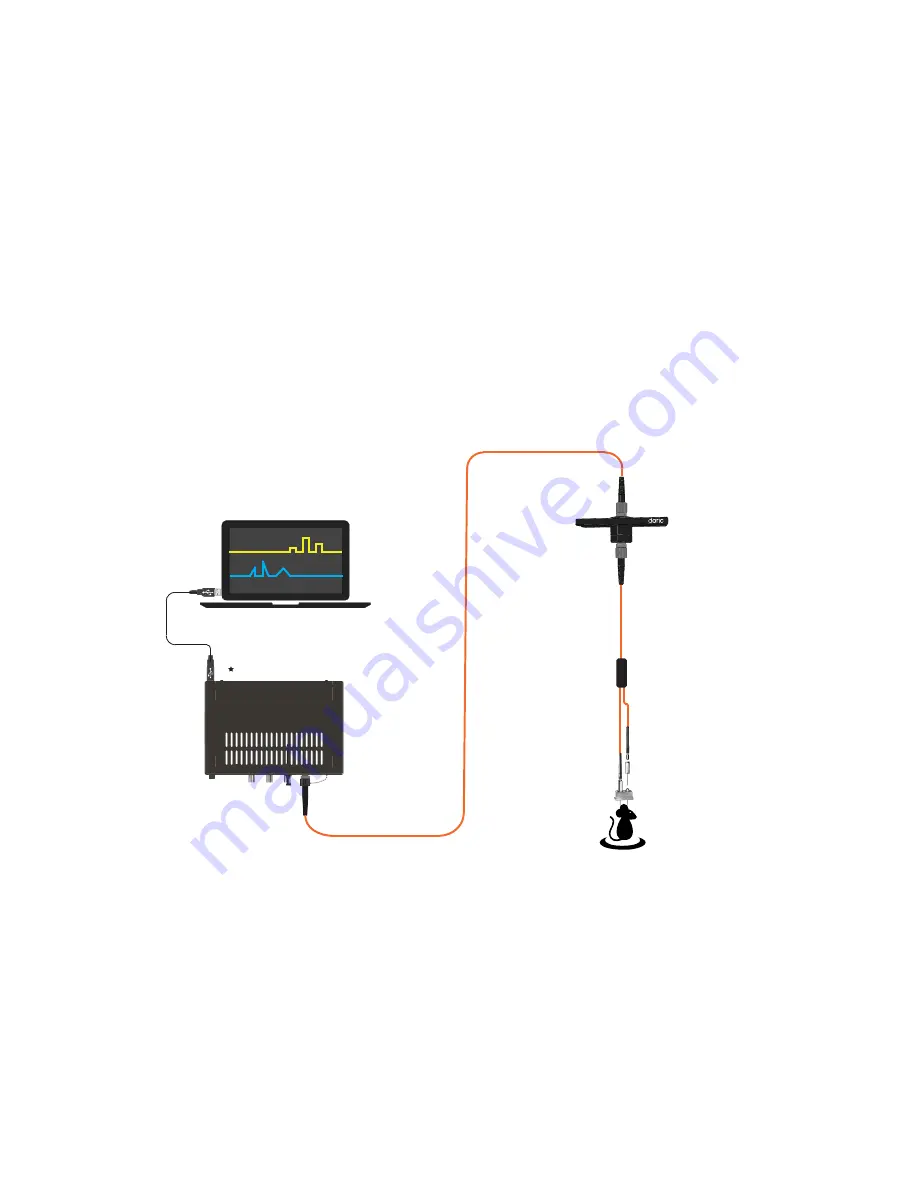
LISER
™/LD 450
Light Source
Fiber optic rotary joint
(FRJ_1x1_FC)
secure to a holder
(Holder_FRJ_small)
Branching fiber optic
patch cord (BFP)
Two ferrule cannula
(TFC)
Doric Neuroscience Studio
FRJ_1x1_FC-FC
Figure 3.1:
System using a
⋆
LISER
TM
& LED/LD Light Source
Chapter 3. Operations Guide
11


