Operation & Maintenance Manual
Installation
18
23221138 (5/08) Rev B
Compressor Discharge Piping
The connection between the compressor package and the receiver must be furnished by the
customer, unless the optional fuel tank/receiver tank module is supplied. It is recommended
the customer use a flexible line of ½" or larger. All piping must be certified safe for the
pressures and temperatures involved.
This unit utilizes a sense line that is connected from the receiver tank to the gauge / switch
port on the compressor. This port is located next to the compressed air discharge on the end
of the compressor. The purpose of this line is to provide a relatively pulsation free, cool, and
stable pressure signal for use by the discharge pressure gauge. The receiver is thus used as
a pulsation damper. This ensures smooth, accurate operation of the gage and extends the life
of this component. This line must be connected for the unit to function.
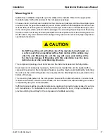
CAUTION
!
Do NOT install a cutoff valve of any type between the discharge of the
compressor module and the receiver tank. Dead-heading the pump can
cause severe internal damage to the pump, drive, or other components.
Receiver Tank Installation
In addition to the unit mounted Receiver/Fuel Tank Module, Doosan Portable Power offers two
different size receiver tank options for the reciprocating compressor modules. These tanks are
intended to be remote mounted either under the vehicle or in a service body compartment. The
10-gallon tank is supplied with band clamps for mounting to the truck’s frame rail, but it can be
mounted elsewhere if needed. The 22-gallon tank has mounting flanges and isolators for
mounting the tank on installer-provided brackets somewhere in or on the body of the truck.
These tank kits are designed for installation versatility. Depending on the application, some of
the components are interchangeable. This feature allows the tanks to be installed in a number
of different configurations.
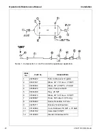
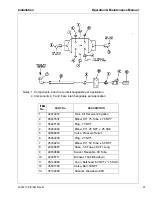
The compressor discharge air should be piped to the tank inlet. Any service air connections
should be taken from the tank outlet. See the tank piping diagrams for further piping
information.
Piping - General
Rmand CM Series Compressors will require customer provided piping from the compressor
module to the hydraulic supply and the air service piping. These hoses are not provided with
the units, as the required lengths of the hoses are dependent on the relative locations of
module in its installed location. It is left to the installer to obtain hoses of the correct type and
length for each installation.
Содержание Ingersoll Rand VHP40RMD
Страница 2: ...2...
Страница 5: ...23221138 5 08 Rev B 5 Safety...
Страница 15: ...23221138 5 08 Rev B 15 Installation...
Страница 23: ...23221138 5 08 Rev B 23 General Data...
Страница 26: ...Operation Maintenance Manual General Data 26 23221138 5 08 Rev B...
Страница 27: ...23221138 5 08 Rev B 27 Operating Instructions...
Страница 35: ...23221138 5 08 Rev B 35 Maintenance Lubrication...
Страница 44: ...44 23221138 5 08 Rev B...
Страница 45: ...23221138 5 08 Rev B 45 Trouble Shooting...

