background image

Operation & Maintenance Manual

Troubleshooting

86


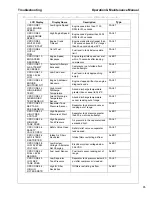
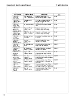
LCD Display 

Display Name 

Description 

Type

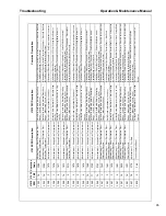
CPR CODE 50  
HIGH SEP  
TANK TEMP  

High Separator 
Tank Temperature  

Separator tank temperature 
greater than or equal to 248

o

F. 

FAULT  

CPR CODE 51  
COMPRESSOR
ID INVALID

Compressor ID 
Invalid

The Titan controller and MidPort
Display do not have a valid 
compressor ID. 

FAULT  

CPR CODE 52  
IQ FILTERS  
RESTRICTED  

IQ Filter Restricted  

IQ filters restricted past usable 
level. 

FAULT  

CPR CODE 53  
SEP TANK  
TEMP SENSOR  

Separator Tank 
Temperature 
Sensor

Separator tank temperature 
sensor reading out of range. 

FAULT  

CPR CODE 54  
REG SYSTEM  
PRES SENSOR

Regulation System 
Pressure Sensor  

Regulation system pressure 
sensor reading out of range. 

FAULT  

CPR CODE 55  
E-STOP
ACTIVATED  

Emergency Stop 
Activated

Emergency Stop button has been 
activated. 

FAULT  

CPR CODE 58  
AMBIENT
TEMP SENSOR  

Ambient
Temperature 
Sensor

Ambient temperature sensor 
reading out of range. 

ALERT  

CPR CODE 61  
IQ FILTER  
PRES ERROR

IQ Filter Pressure 
Error

IQ filter outlet pressure reading 
higher than inlet pressure.  

ALERT  

CPR CODE 63  
IQ DIFF  
PRES SENSOR

IQ Differential 
Pressure Sensor  

IQ differential pressure sensor 
reading out of range. 

ALERT  

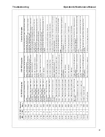
CPR CODE 71  
ENG ECM
COMMS

Engine ECM 
Communication  

Communication between Titan 
controller and engine ECM not 
functional. 

FAULT  

CPR CODE 73  
AUTOSTART  
CTRL COMMS  

Auto Start 
Controller 
Communication  

Communication between Titan 
controller and AutoStart controller 
not functional. 

ALERT  

CPR CODE 75  
IQ TCU  
CTRL COMMS  

IQ TCU Controller 
Communication  

Communication between Titan 
controller and OTC controller not 
functional. 

ALERT  

CPR CODE 76  
CPR
CTRL COMMS  

Compressor 
Controller 
Communication  

Communication between Titan 
controller and Engine Tachometer
with MidPort Display not functional. 

ALERT  

CPR CODE 77 
KEYPAD
COMMS

Keypad 
Communication  

Communication between Titan 
controller and Keypad not 
functional. 

FAULT 

Содержание HP450/VHP400WCU-T4i

Страница 1: ...wer 1293 Glenway Drive Statesville N C 28625 DoosanPortablePower com P N 46614501 07 2012 Rev A This manual contains important safety information Do not destroy this manual This manual must be available to the personnel who operate and maintain this compressor OPERATION and MAINTENANCE MANUAL ...

Страница 2: ...2 ...

Страница 3: ...ssion Control Information 30 Maintenance Log 31 Noise Emission Warranty 31 Introduction 32 Maintenance Schedule 32 A Compressed Air Leaks 32 B Safety and Control Systems 32 C Acoustic Materials 32 D Fasteners 33 E Enclosure Panels 33 F Air Intake and Engine Exhaust 33 G Cooling Systems 33 H Isolation Mounts 33 I Engine Operation 33 J Fuels and Lubricants 33 GENERAL DATA 35 General Data Information...

Страница 4: ...emoval 63 lnspection 63 Reassembly 63 Compressor Oil Separator Element 64 Removal 64 lnspection 64 Reassembly 64 Compressor Oil Cooler Engine Radiator and other Heat Exchangers 65 Air Filter Elements 66 Removal 66 Inspection 66 Reassembly 66 Ventilation 67 Cooling Fan Drive 67 Fuel System 67 Fuel Filter Water Separator 67 Charge Air Cooler Pipework 67 Hoses 67 Electrical System 68 Battery 68 Press...

Страница 5: ...G 79 Introduction 80 Think Before Acting 80 Do the Simplest Things First 80 Double Check Before Disassembly 80 Find and Correct Basic Cause 80 Troubleshooting Chart 81 Diagnostic Codes 85 88 Engine Diagnostic Codes Cummins Engine with CM2250 Controller 89 OPTIONS 103 IQ System 104 Theory of Operation 104 IQ System Configuration 106 Maintenance 107 Filter Replacement 108 ...

Страница 6: ...6 ...

Страница 7: ...7 Foreword ...

Страница 8: ...ible be of a type approved by Portable Power clearly rated for a pressure at least equal to the compressor safety valve setting compatible with the compressor oil accompanied with instructions for safe installation operation and maintenance Details of approved equipment are available from the Portable Power Service departments The use of repair parts other than those included within the approved p...

Страница 9: ...ance requirements explained in this manual be performed at the required intervals Exceeding these intervals may reduce the reliability of the compressor The purpose of this manual is to train the operator with functions operation and basic service and maintenance requirements of the compressor During the preparation of this manual every effort was made to ensure the accuracy and adequacy of the co...

Страница 10: ...Operation Maintenance Manual Foreword 10 ...

Страница 11: ...11 Safety ...

Страница 12: ... should be checked for total security All components which are loose damaged or unserviceable must be rectified without delay Air discharged from this compressor may contain carbon monoxide or other contaminants which will cause serious injury or death Do not breathe discharged air This compressor produces loud noise with the doors open or service valve vented Extended exposure to loud noise can c...

Страница 13: ...r supply line at tool or vent valve before performing any service or maintenance Discharged air contains a very small percentage of compressor lubricating oil and care should be taken to ensure downstream equipment is compatible If discharged air is to be ultimately released into a confined space adequate ventilation must be provided When using compressed air always use appropriate personal protec...

Страница 14: ... the exhaust aftertreatment system and controls Materials The following substances may be produced during the operation of this compressor brake lining dust engine exhaust fumes WARNING Avoid inhalation of material substances Ensure that adequate ventilation of the cooling system and exhaust gases is maintained at all times The following substances are used in the manufacture of this compressor an...

Страница 15: ...ls Battery A battery contains sulfuric acid and can produce gases which are corrosive and potentially explosive Avoid contact with skin eyes and clothing In case of contact flush area immediately with water WARNING Do not attempt to jump start a frozen battery since this may cause it to explode Exercise extreme caution when using an external method to jump start a unit Verify the electrical system...

Страница 16: ...ight towing hitch and electrical supply are all suitable to provide safe and stable towing at speeds either up to the legal maximum for the country in which it is being towed or as specified for the compressor model if lower than the legal maximum Do not exceed gross vehicle weight rating Before towing the compressor ensure the tires and towing hitch are in a serviceable condition and tires are pr...

Страница 17: ...ing vehicle Ensure cable length is as short as possible while still allowing enough slackness for the towed compressor to articulate without the brake being applied Attach safety chains to the towing vehicle at substantial anchorage points of suitable strength Ensure effective chain length is as short as possible while still allowing normal articulation of the towed compressor and proper operation...

Страница 18: ...und Indicates the presence of a hazard which WILL cause serious injury death or property damage if ignored WARNING Orange Background Indicates the presence of a hazard which CAN cause serious injury death or property damage if ignored CAUTION Yellow Background Indicates the presence of a hazard which WILL or CAN cause injury or property damage if ignored NOTICE Blue Background Indicates important ...

Страница 19: ...cals are identified by the decal heading DANGER WARNING CAUTION NOTICE Decal part numbers are located in the lower right hand corner of each decal and are also listed in the compressor Parts Manual Submit orders for Safety Decals to the Statesville Parts Service Dept The no charge order should contain only Safety Decals Help promote product safety Ensure decals are present on the compressor Replac...

Страница 20: ... C attach safety device OSHA Valve at source of When using air tools air supply for each tool Close service valve and operate tool to vent trapped air before performing any service Do not breathe this air 54568795 REV C 4655988 54749163 REV C 5 S 3M Hot ...

Страница 21: ...Safety Operation Maintenance Manual 21 ...

Страница 22: ...Operation Maintenance Manual Safety 22 ...

Страница 23: ...Safety Operation Maintenance Manual 23 ...

Страница 24: ...ning WARNING Electrical Shock Risk WARNING Pressurized Component or System WARNING Hot Surface WARNING Pressure Control WARNING Corrosion Risk WARNING Air Gas Flow or Air Discharge WARNING Pressurized Vessel WARNING Hot and harmful exhaust gas WARNING Maintain correct tire pressure Refer to the GENERAL INFORMATION section of this manua ...

Страница 25: ...ance Manual o WARNING Do not undertake any maintenance on this machine until the electrical supply is disconnected and the air pressure is totally relieved WARNING Consult the Operation and Maintenance manual before commencing any maintenance Do not Breathe the compressed air from this machine Do not remove the Operation and Maintenance manual and manual holder from this machine Do not stack Do no...

Страница 26: ...rking Brake Rough Service Designation Wet Location Operation Read the Operation and Maintenance manual before operation or maintenance of this machine is undertaken When parking use prop stand handbrake and wheel chocks Compressor oil filling Lifting point ON power OFF power Use fork lift truck from this side only Emergency stop Tie down point Do not exceed trailer speed limit No open flames Do no...

Страница 27: ...d protective shield Oil drain Engine Oil Fuel level point Pressure control Malfunction Battery charging condition Low pressure High pressure Engine malfunction High Compressor Temperature Compressor malfunction Low engine oil pressure Engine high temperature ...

Страница 28: ...Operation Maintenance Manual Safety 28 ...

Страница 29: ...29 Noise Emission ...

Страница 30: ...thereof b the air intake system or parts thereof c enclosure or parts thereof 2 Removal of any of the following a fan shroud b vibration mounts c sound absorption material 3 Operation of the compressor with any of the enclosure doors open Compressor Noise Emission Control Information A The removal or rendering inoperative other than for the purpose of maintenance repair or replacement of any noise...

Страница 31: ...ent purchaser that this air compressor was designed built and equipped to conform at the time of sale to the first retail purchaser with all applicable U S EPA Noise Control Regulations This warranty is not limited to any particular part component or system of the air compressor Defects in the design assembly or in any part component or system of the compressor which at the time of sale to the fir...

Страница 32: ...immediately and correct the leak s B Safety and Control Systems Repair or replace all safety and control systems or circuits as malfunction occurs No compressor should be operated with either system bypassed disabled or nonfunctional C Acoustic Materials In daily inspections observe these materials Maintain all acoustic material as nearly as possible in its original condition Repair or replace all...

Страница 33: ...systems should be inspected after each 100 hours of operation for loose damaged or deteriorated components Repairs or replacements should be made before the next period of use G Cooling Systems All components of the cooling system for engine water and compressor oil should be inspected every 250 hours of use Any discrepancies found should be corrected before placing the compressor back in operatio...

Страница 34: ...n Maintenance Manual Noise Emission 34 MAINTENANCE RECORD FOR NOISE EMISSION CONTROL AND EXTENDED WARRANTY ITEM NO DESCRIPTION OF WORK HOURMETER READING MAINT INSPECT DATE LOCATION CITY STATE WORK DONE BY NAME ...

Страница 35: ...35 General Data ...

Страница 36: ...mmins Model QSB 6 7 Rated Power at Full Load Speed hp kw 173 129 2200 RPM Full Load Speed rpm 2200 1950 2200 1950 Idle Speed rpm 1500 Idle Speed warm up rpm 1600 Electrical System 24V FLUID CAPACITIES U S Gallons liters Compressor Oil 9 5 36 Engine Oil including filter 4 6 17 5 Engine Coolant 7 0 26 5 Fuel Tank 73 276 AMBIENT TEMPERATURE RANGE With Standard Features 10 F 12 C to 120 F 49 C With Re...

Страница 37: ...EMENTS WEIGHTS Overall Length feet meters incl bumper 14 8 4 5 Overall Height feet meters 6 7 2 0 Overall Width feet meters 6 5 1 98 Operating Weight with fuel lb kg 4700 2132 Shipping Weight less fuel lb kg 4178 1895 RUNNING GEAR Tire Size ST235 80R16 Tire Inflation Pressure psi bar 65 4 5 Maximum Towing Speed mph km hr 65 105 ...

Страница 38: ...Operating Maintenance Manual General Data 38 ...

Страница 39: ...39 Operating Instructions ...

Страница 40: ...uge Indicates airend discharge temperature 4 Engine Coolant Temperature Gauge Indicates engine coolant temperature 5 Fuel Level Gauge Indicates level of fuel in tank 6 Engine Oil Pressure Gauge Indicates engine oil pressure PSI 7 MidPort Displays compressor operating parameters and diagnostic codes 8 Main Power Button Start and Shutdown compressor control system and gauge panel 9 KeyPad Used to st...

Страница 41: ...s menu choices or increases a value until the end of the parameter list menu choices or maximum parameter value is reached DOWN The DOWN Button functions identical to the UP Button with the exception that its direction for all displays menu choices and values is down or decreasing ENTER Pressing and releasing this button provides enter functionality when the display requires you to choose a menu i...

Страница 42: ...in until acknowledged by the user This will continue to occur as long as the Fault is active See Figure 1 Figure 1 When present an ALERT with the number of alert conditions will popup on the screen the user will press the UP or DOWN Button to display the alert or press the ENTER Button to acknowledge an alert has occurred If there are multiple alerts pressing the DOWN Button will scroll through th...

Страница 43: ...hours or it remains at 0 hours the SERVICE DUE display will appear every hour To disable the user can reset the hours to the OFF position by decreasing the value to OFF See Figure 3 Figure 3 The service intervals can be changed by pressing the ENTER Button while on the default screen that displays the engine hours Using the UP or DOWN Buttons to highlight the desired interval and press the ENTER B...

Страница 44: ...nu To access the Setup Menu press and hold the ENTER Button while the Default Screen of Engine Hours is displayed until the Main Menu appears Scroll to the Setup option using the DOWN Button then press the ENTER Button Use the DOWN or UP Buttons to highlight the chosen unit and PRESS the ENTER Button to select To return to the Default Screen of Engine Hours use the DOWN Button to highlight the Mai...

Страница 45: ...uously loops through the Quick View Screens i e when the last screen is reached pressing the DOWN Button displays the first screen and vice versa Figure 6 Note 1 Only the parameters that are available from the engine or compressor will be displayed Note 2 Unit times out after 3 minutes of inactivity and returns to the Default Screen of Engine Hours Note 3 Pressing the Enter Button while viewing a ...

Страница 46: ...ed until the Main Menu appears 2 Scroll to the Setup option using the DOWN Button and press the ENTER Button 3 Scroll to the Display option using the DOWN Button and press the ENTER Button 4 Use the DOWN or UP Buttons to highlight and the ENTER Button to select the desired display setting See Figure 7 5 To return to the Default Screen of Engine Hours use the DOWN Button to highlight the Main Scree...

Страница 47: ...art message is displayed the engine will receive heat from the intake heater if required It is best to start the engine immediately after the Wait to Start message changes to Engine Total Hours Lifting The central lifting bail allows the compressor to be lifted from a single point Use hoist or crane capable of lifting compressor weight See General Data WARNING Falling off the compressor can cause ...

Страница 48: ...specially to avoid strain on air discharge piping Chock wheels and or set parking brake Ensure all transport and packing materials are removed Compressor Mounting Portable compressors which are modified to remove the running gear and mount the compressor directly to trailers truck beds or frames etc may experience failure of the enclosure frame and or other components It is necessary to isolate th...

Страница 49: ...ipping if a connection fails Whipchecks are to be constructed of woven stainless steel galvanized steel wire rope or chain with a minimum strength adequate for the supplied pressure and hose diameter Whipchecks must be fastened to suitable mounting points or shackles The mounts and or shackles are to be of the same or greater strength as the whipchecks An engineer should be consulted about suitabi...

Страница 50: ...en using an external method to jumpstart a unit Verify the electrical systems on the weak battery system and the external jump system are the same voltage type system 12VDC or 24VDC Connect the Positive terminal of the external system to the Positive terminal on the weak system Connect the Negative terminal of the external system to the Negative terminal of the weak system Always disconnect the tw...

Страница 51: ...perator Manual for fuel specifications NOTICE To minimize condensation water in the fuel tank it is recommended to fill the tank at the end of each day NOTE Compressor will not allow engine starting if the fuel level is below the minimum fuel shut off level WARNING Compressor produces loud noise with doors open Extended exposure to loud noise can cause hearing loss Wear hearing protection when doo...

Страница 52: ...to the Control Panel for starting the compressor 1 Press the Main Power Button 2 When the Wait To Start message on the MidPort changes to Total Engine Hours press and release Green Start Button 3 Engine will crank until engine starts or engine starting time limit is reached The first Green light on the Start Button will illuminate 4 If engine fails to start press Main Power Button to remove power ...

Страница 53: ...d as low as 80 psi 2 The High Pressure Mode is activated by pressing the Hi Pressure Button In High Pressure Mode the compressor will regulate according to air demand between 0 and rated air delivery See General Data at the higher regulated set pressure See General Data The regulated set pressure of this mode can be regulated as low as 80 psi The mode of the compressor can be changed between the L...

Страница 54: ...nutes if ambient temperature is 45 F 7 C or below of the keypad use the compressor will automatically shut off NOTICE Failure to allow turbocharger cool down prior to stopping can cause turbocharger damage NOTICE This compressor is equipped with a battery disconnect switch which disconnects power for long term storage The switch is located on the fuel tank side Do not use the battery disconnect sw...

Страница 55: ...ION Never allow the compressor to sit stopped with pressure in the separator tank or piping As a precaution open the Service Valve Decommissioning When the compressor is to be permanently decommissioned or dismantled it is important to ensure that all hazard risk are either eliminated or recepient of the compressor notified In particular Do not destroy batteries or components containing asbestos w...

Страница 56: ...Operating Maintenance Manual Operating Instructions 56 ...

Страница 57: ...57 Maintenance ...

Страница 58: ... accidentally 2 If the Automatic Blowdown Valve fails to operate pressure must be gradually relieved by operating the Manual Blowdown Valve 3 The discharge pipe manifold area is depressurized by opening the discharge valve while keeping clear of any air flow 4 Maintenance personnel are adequately trained competent and have read the Operation and Maintenance Manual WARNING Pressure will remain in t...

Страница 59: ... Maintenance Work is in Progress are posted in a position that can be clearly seen Upon completion of maintenance task and prior to returning the compressor into service ensure 1 The compressor is suitably tested 2 All guards and safety protection devices are refitted 3 All panels are replaced canopy and doors closed 4 Hazardous materials are effectively contained and disposed of NOTICE The mainte...

Страница 60: ...ator Filler Cap C Emergency Stop T Lubricator Fill C Air Cleaner Precleaner Dumps C Fan Alternator Belts C Battery Connections Electrolyte C Hoses Oil Air Intake etc C Automatic Shutdown System C Air Cleaner System C Compressor Oil Cooler Exterior C Engine Rad Oil Cooler Exterior C Engine Charge Air Cooler Exterior C Aftercooler Exterior C Safety Valve C Fasteners Guards C Disregard if not appropr...

Страница 61: ...ment R Separator Tank Exterior 2 CR Engine Coolant C R Engine Crankcase Breather Element R Water Pump Grease G Shutdown Switch Settings T Scavenge Orifice Related Parts C Scavenge Line C Valve Clearance Check C Feed Pump Strainer Cleaning C Injection Nozzle Check C Disregard if not appropriate for this particular compressor D Drain 1 or 3000 miles 5000km whichever is the sooner G Grease 2 or as de...

Страница 62: ...g gear bolts 1 C Wheels Bearings Seals etc C G 2 Yrs 4 Yrs 6 Yrs Safety valve C Hoses R Separator tank 2 interior C Disregard if not appropriate for this particular compressor D Drain 1 or 3000 miles 5000km whichever is the sooner G Grease 2 or as defined by local or national legislation R Replace C Check adjust clean or replace as necessary T Test CBT Check before towing W I or when indicated if ...

Страница 63: ...ING in the OPERATING INSTRUCTIONS section of this manual Clean the exterior of the filter housing and remove the spin on element lnspection Inspect the oil filter head to be sure the gasket was removed with the oil filter element Clean the gasket seal area on the oil filter head CAUTION If there is any indication of the formation of varnishes shellacs or lacquers on the filter element it is a warn...

Страница 64: ... been completely relieved of all air pressure Refer to STOPPING in the OPERATING INSTRUCTIONS section of this manual Disconnect all hoses and tubes from the separator tank cover plate Remove the drop tube from the separator tank cover plate and remove the cover plate Remove the separator element lnspection Examine the separator element Examine all hoses and tubes and replace if necessary Reassembl...

Страница 65: ... It is recommended that the heat exchangers be cleaned per the Maintenance Schedule in this manual by a jet of compressed air This should remove any accumulation of oil grease and dirt from the exterior cores of the cooler so the entire cooling area can radiate heat into the air stream Access doors are located on each side of the compressor to provide access to aid in cleaning the heat exchangers ...

Страница 66: ...e and replace element s when the compressor is running Clean the exterior of the filter housing and remove the filter element by following instructions on the filter If the safety element is to be replaced thoroughly clean the interior of the filter housing prior to removing the safety element Inspection Check for cracks holes or any other damage to the element by holding it up to a light source o...

Страница 67: ...lated in the tank s Refer to Maintenance Schedule Fuel Filter Water Separator The fuel filter water separator contains a filter element which should be replaced as required by the Maintenance Schedule Charge Air Cooler Pipework Foreign particles can damage the engine and turbocharger Maintain internal cleanliness and integrity of the air filtration intake piping and charge air cooler piping to hel...

Страница 68: ...eep the battery terminals and cable clamps clean and lightly coated with petroleum jelly to prevent corrosion The battery restraint should be kept tight enough to prevent the battery from moving Pressure System Regularly it is necessary to inspect the external surfaces of the pressure system from the Airend through to the Service Valve s including hoses tubes tube fittings and the separator tank f...

Страница 69: ... the Maintenance Schedule in this section for service intervals NOTE If the compressor has been operating under adverse conditions or has suffered long shutdown periods more frequent service intervals will be required WARNING DO NOT under any circumstances remove any drain plugs or the oil filler plug from the compressor lubricating and cooling system without first ensuring the compressor is stopp...

Страница 70: ...efer to the Portable Compressor Oil Chart Running Gear Wheel Bearings Wheel bearings should be greased per the Maintenance Schedule in this manual The type of grease used should conform to specifications below Grease Thickener Type Lithium Complex Dropping Point 215 C 419 F Minimum Consistency NLGI No 2 Additives EP Corrosion Oxidation Inhibitors Viscosity Index 80 Minimum ...

Страница 71: ...arting Unit 5 Push the Service Air Button on the Control Panel The unit should speed up and then unload and drop back to IDLE With the unit unloaded turn the adjusting screw on the Low Pressure Regulator clockwise until the discharge pressure gauge indicates 25 psi over the rated pressure Tighten the pressure regulator jam nut 6 To adjust the high pressure regulation repeat Step 5 on High Pressure...

Страница 72: ...Operation Maintenance Manual Maintenance 72 Torque Values TABLE 1 INCH FASTENERS SAEJ249 SAEJ249 ...

Страница 73: ...t Metric 1 2 lug nuts Torque Ft Lbs Torque N m Torque ft Lbs 13 Wheel 80 90 15 Wheel 105 115 M12 Bolts 85 95 62 70 16 Wheel 105 115 M14 Bolts 145 155 107 115 16 5 Wheel 105 115 M16 Bolts 175 185 129 137 5 8 Lug Nuts M18 Bolts 205 215 151 159 16 Wheel 190 210 17 Wheel 190 210 9 16 Clamp nuts Demountable Wheels 14 5 Wheel 105 115 TABLE 3 TABLE 3 WHEEL TORQUE CHART ...

Страница 74: ...Operation Maintenance Manual Maintenance 74 ...

Страница 75: ...75 Lubrication ...

Страница 76: ...ltration for the compressor Compressor Oil Change These compressors are furnished with an initial supply of oil sufficient to allow operation until the first service interval indicated in the Maintenance Schedule If a compressor has been drained of all oil it must be refilled with new oil before it is placed in operation Refer to specifications in the Portable Compressor Oil Chart NOTICE Some oil ...

Страница 77: ... has suffered long shutdown periods more frequent service intervals will be required If the oil is drained immediately after the compressor has been run for some time most of the sediment will be in suspension and therefore will drain more readily However the oil will be hot and care must be taken to avoid contact with the skin or eyes After the compressor has been drained of all old oil close the...

Страница 78: ...rnative oils Preferred Oils Use of these oils with Doosan branded filters can extend airend warranty Refer to the warranty policy for details or contact your representative Table 1 Rated Operating Pressure Ambient Temperature Compressor Oil Specification 100 psi to 200 psi 6 9 to 13 8 bar 10 F to 120 F 23 C to 49 C Preferred PRO TEC Alternate ISO Viscosity Grade 46 PAO with rust and oxidation inhi...

Страница 79: ...79 Troubleshooting ...

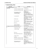
Страница 80: ...previous maintenance work has been done 4 If the compressor will still operate is it safe to continue operating to make further checks Do the Simplest Things First Most problems are simple and easily corrected For example most complaints are low capacity which may be caused by too low an engine speed or compressor overheats which may be caused by low oil level Always check the easiest and most obv...

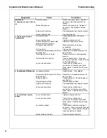
Страница 81: ...onic Service Manual Engine malfunctioning See troubleshooting in Engine manual Airend malfunctioning See Complaint 6 2 Compressor won t start or Battery disconnect switch off Check switch position and operation 2 Compressor won t start or run Battery disconnect switch off Check switch position and operation Emergency stop pushed Check emergency stop switch position and operation Low battery voltag...

Страница 82: ...Close and secure access panels Check for loose or missing belly pans Loose wire connection Check wires at switches and connectors to find loose connection Make repairs See Electronic Service Manual 4 Low Engine Oil Pressure Low engine oil level Check oil level If low add oil 4 Low Engine Oil Pressure o e g e o e e C ec o e e o add o Compressor tilted beyond out of level operating limit Reposition ...

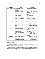
Страница 83: ...tioning compressor oil thermostat Replace thermostat element in conventional bypass valve if equipped Loose or broken belts Tighten or replace belt set Replace valve Malfunctioning minimum pressure valve Repair or replace valve Blocked or restricted oil lines Clean by flushing or replace lines Airend malfunctioning See Complaints 11 12 g p 7 Low engine speed Clogged fuel filters Service fuel filte...

Страница 84: ...C electric heaters if equipped L Plugged vent leak Clean and or replace 12 Safety valve opens Operating pressure too high Reduce pressure to rated operating pressure Malfunctioning inlet unloader butterfl Inspect valve Make adjustments per g y valve p j p this manual Defective safety valve Replace safety valve Compressor will not unload fast enough Check pressure regulator Check regulation lines f...

Страница 85: ...EMP High Airend Discharge Temperature Airend discharge temperature greater than or equal to 248o F FAULT CPR CODE 32 AIREND DISC TEMP SENSOR Airend Discharge Temperature Sensor Airend discharge temperature sensor reading out of range FAULT CPR CODE 33 SEP TANK PRES SENSOR Separator Tank Pressure Sensor Separator tank pressure sensor reading out of range FAULT CPR CODE 34 HIGH PRES AT START High Se...

Страница 86: ...P SENSOR Ambient Temperature Sensor Ambient temperature sensor reading out of range ALERT CPR CODE 61 IQ FILTER PRES ERROR IQ Filter Pressure Error IQ filter outlet pressure reading higher than inlet pressure ALERT CPR CODE 63 IQ DIFF PRES SENSOR IQ Differential Pressure Sensor IQ differential pressure sensor reading out of range ALERT CPR CODE 71 ENG ECM COMMS Engine ECM Communication Communicati...

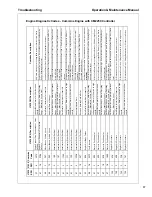
Страница 87: ...pdate Rate SAE J1939 Multiplexed Accelerator Pedal or Lever Sensor System Abnormal update rate 91 19 287 Accelerator Pedal Position 1 Received Network Data in Error SAE J1939 Multiplexing Accelerator Pedal or Lever Sensor System Error Received Network Data In Error 93 2 528 Engine Net Brake Torque Data Erratic Intermittent or Incorrect Auxiliary Constrained Operation Curve Validation Switch Data E...

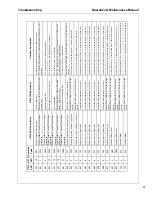
Страница 88: ...perational Range Most Severe Level Coolant Level Low Data Valid but Below Normal Operational Range Most Severe Level 111 2 422 Engine Coolant Level Data Erratic Intermittent or Incorrect Coolant Level Data Erratic Intermittent or Incorrect 111 3 195 Engine Coolant Level Voltage Above Normal or Shorted to High Source Coolant Level Sensor Circuit Voltage Above Normal or Shorted to High Source 111 4 ...

Страница 89: ...ntermittent or Incorrect Engine Speed Position Sensor 1 Data Erratic Intermittent or Incorrect 191 9 3328 Transmission Output Shaft Speed Abnormal Update Rate Transmission Output Shaft Speed Abnormal update rate 191 16 349 Transmission Output Shaft Speed Data Valid but Above Normal Operating Range Moderately Severe Level Transmission Output Shaft Speed Data Valid but Above Normal Operational Range...

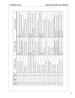
Страница 90: ...urce 611 16 2292 System Diagnostic Code 1 Data Valid but Above Normal Operating Range Moderately Severe Level Fuel Inlet Meter Device Data Valid but Above Normal Operational Range Moderately Severe Level 611 18 2293 System Diagnostic Code 1 Data Valid but Below Normal Operating Range Moderately Severe Level Fuel Inlet Meter Device Flow Demand Lower Than Expected Data Valid But Below Normal Operati...

Страница 91: ... Engine Fan Clutch 1 Output Device Driver Voltage Below Normal or Shorted to Low Source Fan Control Circuit Voltage Below Normal or Shorted to Low Source 651 5 322 Engine Injector Cylinder 01 Current Below Normal or Open Circuit Injector Solenoid Cylinder 1 Circuit Current Below Normal or Open Circuit 652 5 331 Engine Injector Cylinder 02 Current Below Normal or Open Circuit Injector Solenoid Cyli...

Страница 92: ... Engine Compression Brake Output 2 Voltage Above Normal or Shorted to High Source Engine Brake Actuator Driver Output 2 Circuit Voltage Above Normal or Shorted to High Source 1073 4 2363 Engine Compression Brake Output 2 Voltage Below Normal or Shorted to Low Source Engine Brake Actuator Driver Output 2 Circuit Voltage Below Normal or Shorted to Low Source Source to Low Source 1075 3 2265 Engine E...

Страница 93: ...rmittent or Incorrect 1378 31 649 Engine Oil Change Interval Not Available or Condition Exists Change Lubricating Oil and Filter Condition Exists 1388 3 297 Auxiliary Pressure 2 Voltage Above Normal or Shorted to High Source Auxiliary Pressure Sensor Input 2 Circuit Voltage Above Normal or Shorted to High Source 1388 4 298 Auxiliary Pressure 2 Voltage Below Normal or Shorted to Low Source Auxiliar...

Страница 94: ...el Oxidation Catalyst System Data Valid But Below Normal Operating Range Least Severe Level 3050 18 1691 Catalyst Bank 1 System Monitor Data Valid but Below Normal Operating Range Moderately Severe Level Aftertreatment Diesel Oxidation Catalyst System Data Valid But Below Normal Operating Range Moderately Severe Level Range Moderately Severe Level Operating Range Moderately Severe Level 3058 31 27...

Страница 95: ...t Gas Temperature 2 Data Valid but Above Normal Operating Range Moderately Severe Level Aftertreatment Exhaust Gas Temperature 2 Data Valid But Above Normal Operating Range Moderately Severe Level 3249 17 2742 Aftertreatment 1 Exhaust Gas Temperature 2 Data Valid but Below Normal Operating Range Least Severe Level Aftertreatment Exhaust Gas Temperature 2 Data Valid But Below Normal Operating Range...

Страница 96: ...ormal Operating Range Least Severe Level 3556 16 2728 Aftertreatment 1 Hydrocarbon Doser Data Valid but Above Normal Operating Range Moderately Severe Level Aftertreatment Fuel Injector 1 Data Valid But Above Normal Operating Range Moderately Severe Level Range Moderately Severe Level Moderately Severe Level 3597 3 1939 ECU Power Output Supply Voltage 1 Voltage Above Normal or Shorted to High Sour...

Страница 97: ...sel Oxidation Catalyst Missing Not Available or Condition Exists Aftertreatment Diesel Oxidation Catalyst Missing Condition Exists 5246 0 3712 Aftertreatment SCR Operator Inducement Severity Data Valid but Above Normal Operational Range Most Severe Level Aftertreatment SCR Operator Inducement Data valid but above normal operational range Most Severe Level 5421 5 3922 Engine Turbocharger Wastegate ...

Страница 98: ... Above Normal or Shorted to High Source Engine Exhaust Gas Recirculation EGR Mixer Inlet Temperature Sensor Circuit Voltage Above Normal or Shorted to High Source 520442 4 3296 Engine Exhaust Gas Recirculation EGR Mixer Inlet Temperature Sensor Circuit Voltage Below Normal or Shorted to Low Source Engine Exhaust Gas Recirculation EGR Mixer Inlet Temperature Sensor Circuit Voltage Below Normal or S...

Страница 99: ...Troubleshooting Operation Maintenance Manual 99 ...

Страница 100: ...Operation Maintenance Manual Troubleshooting 100 ...

Страница 101: ...103 Options ...

Страница 102: ...manual valving One path allows Standard Operation which bypasses the IQ System and delivers air quality equivalent to a standard oil flooded portable compressor If the IQ System is enabled by proper setting of the selector valve the compressed air first enters the aftercooler The compressed air and condensate water with a small amount of compressor oil exits the aftercooler and enters the moisture...

Страница 103: ...ation to provide full rated pressure at the Service Valve when the IQ System is enabled This will result in operation at excessive horsepower levels causing overheating reduced engine life and reduced airend life NOTICE Keep all doors and panels closed during operation to direct proper flow of cooling air across the aftercooler and maintain aftercooling performance ...

Страница 104: ... System Configuration IQ System Active Standard Operation IQ System Bypassed 1 Separator Tank 6 Primary IQ Filter 2 Minimum Pressure Valve 7 Secondary IQ FIlter 3 3 Way Selector Valve 8 Check Valve 4 Aftercooler 9 Service Valve 5 Water Separator ...

Страница 105: ...residue Verify the orifices below the Y strainers are not clogged Verify the piping from the orifice purge points to the exhaust system is not clogged CAUTION Blockage of the Y strainers orifices or piping can result in flooding of the vessels with condensate If flooding occurs excessive condensate may enter the airstream and could result in damage to downstream equipment Yearly Maintenance The no...

Страница 106: ...tial loosening taking care to prevent the housing from falling Remove and replace the filter element being careful not to damage outer wrap Verify the part number and positions of new element vs old element as the two IQ filter stages are of different media Put a small amount of petroleum jelly or other non synthetic grease on the element O Ring to aid installation into the filter head Replace hou...

Страница 107: ...Revision History Rev EC Number Comments A CN023581 Original release ...

Страница 108: ... 2011 Doosan Infracore Portable Power Printed in the U S A Doosan Infracore Portable Power 1293 Glenway Drive Statesville N C 28625 www doosanportablepower com ...

Отзывы: