Doosan G20P-3 Скачать руководство пользователя страница 20

- 19 -

LP Engine G430 (3.0L)

Specifications

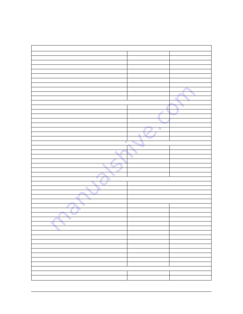
Engine Mechanical Specifications (2 of 2)

Crankshaft

Crankshaft Journal Diameter (All)
Crankshaft Journal Taper Production
Crankshaft Journal Taper Service Limit
Crankshaft Journal Out-of-Round Production
Crankshaft Journal Out-of-Round Service Limit
Crankshaft Bearing Clearance Production #1-#4
Crankshaft Bearing Clearance Production #5
Crankshaft Bearing Clearance Service Limit #1-#4
Crankshaft Bearing Clearance Service Limit #5
Crankshaft End Play
Crankshaft Sprocket Runout

Connecting Rod

Connecting Rod Journal Diameter
Connecting Rod Journal Taper Production
Connecting Rod Journal Taper Service Limit
Connecting Rod Journal Out-of-Round Production
Connecting Rod Journal Out-of-Round Service Limit
Rod Bearing Clearance Production
Rod Bearing Clearance Service Limit
Rod Side Clearance

Camshaft

Journal diameter
End Play
Camshaft Sprocket Runout
Timing Sprocket Teeth Backlash
Lobe Lift Intake
Lobe Lift Exhaust
Lobe Lift Service Limit

Valve System

Valve Lifter

Hydraulic

Valve Rocker Arm Ratio

1.75:1

Valve Lash

Half to One Turn Down From Zero Lash

Face Angle

45 Degrees

Seat Angle

46 Degrees

Seat Runout
Seat Width Intake
Seat Width Exhaust
Stem Clearance Intake Production
Stem Clearance Exhaust Production
Stem Clearance Intake Service Limit
Stem Clearance Exhaust Service Limit
Valve Spring Free Length
Valve Spring Pressure Closed
Valve Spring Pressure Open
Valve Spring Installed  Height Intake
Valve Spring Installed Height Exhaust
Valve Lift Intake
Valve Lift Exhaust

Cylinder Head Warpage

Cylinder Head Deck (measured within a 152.4 mm (6.0 in) area)
Cylinder Head Deck (measuring the overall length of the cylinder head)

58.3666-58.4047 mm

0.005 mm (Maximum)

0.0254 mm (Maximum)

0.005 mm (Maximum)

0.0254 mm (Maximum)

0.0254-0.06096 mm

0.0406-0.0889 mm
0.0254-0.0635 mm
0.0381-0.0889 mm

0.05-0.1524 mm

0.07 mm (Maximum)

53.2892-53.3273 mm

0.00762 mm (Maximum)

0.0254 mm (Maximum)

0.005 mm (Maximum)

0.0254 mm (Maximum)

0.04318-0.06858 mm

0.0762 mm (Maximum)

0.1524-0.4318 mm

47.440-47.490 mm
0.0762-0.2032 mm

0.1 mm (Maximum)

0.10-0.15 mm

6.4247 mm
6.4247 mm

L

0.0254 mm

0.05 mm (Maximum)

1.27-1.778 mm

1.524-2.032 mm

0.0254-0.06858 mm

0.01778-0.06858 mm

0.09398 mm (Maximum)

0.1193 mm (Maximum)

52.324 mm

444-490 N at 40.89 mm
925-987 N at 30.99 mm

41.91 mm
41.91 mm

11.25 mm
11.25 mm

0.0762 mm
0.1778 mm

2.2979-2.2994 in

0.0002 in (Maximum)

0.001 in (Maximum)

0.0002 in (Maximum)

0.001 in (Maximum)

0.001-0.0024 in

0.0016-0.0035 in

0.001-0.0025 in

0.0015-0.0035 in

0.002-0.006 in

0.003 in (Maximum)

2.0980-2.0995 in

0.0003 in (Maximum)

0.001 in (Maximum)

0.0002 in (Maximum)

0.001 in (Maximum)

0.0017-0.0027 in

0.003 in (Maximum)

0.006-0.017 in

1.8677-1.8697 in

0.003-0.008 in

0.004 in (Maximum)

0.004-0.006 in

0.25294
0.25294

L

0.001 in

0.002 in (Maximum)

0.050-0.070 in
0.060-0.080 in

0.001-0.0027 in

0.0007-0.0027 in

0.0037 in (Maximum)
0.0047 in (Maximum)

2.06 in

100-110 lb at 1.61 in

208-222 lb at 1.22 in

1.65 in
1.65 in

0.443 in
0.443 in

0.003 in
0.007 in

Содержание G20P-3

Страница 1: ...G430 LP Engine Standard Version Low Emission Version G20P 3 G25P 3 G30P 3 GC20P 3 GC25P 3 GC30P 3 SB4005E01 Oct 2001 Service Manual...

Страница 2: ...ollowing symbol Improper operation lubrication maintenance or repair of this product can be dangerous and could result in injury or death Do not operate or perform any lubrication maintenance or repai...

Страница 3: ......

Страница 4: ...ce spark plugs 23 Replace LP fuel filter Element 23 Test fuel lock electric 24 Inspect pressure regulaator vaproizer 24 Inspect LP mixer standard LP truck 24 Inspect variable venturi air fuel mixer lo...

Страница 5: ...Visual Inspection 105 Cooling System Tests 105 Thermostat 107 Cooling System Heat Problems 108 Cooling System Recommendation 108 Belt Adjustment 110 V Belt Diagnosis 110 Service Procedures 111 Drainin...

Страница 6: ...il Pump Assemble 156 Cylinder Head Disassemble 157 Cylinder Head Clean and Inspect 158 Valve Guide Reaming Valve and Seat Grinding 160 Rocker Arm Stud Removal and Installation 162 Cylinder Head Assemb...

Страница 7: ......

Страница 8: ...s of ignition are not only open flames but include electrical switches such as air compressor relays and other shop equipment such as bench grinders Adequate ventilation is required before working on...

Страница 9: ...ration of not over 1 5th the lower level of flammability 0 4 in air This is achieved by adding 1 0 s of ethyl mercaptan or 1 0 s of thiophane or 1 4 s of amyl mercaptan per 10 000 gallons of LPG There...

Страница 10: ...degrees will only make 86 horsepower breathing air at 200 degrees This decrease in power can be explained by the fact that an engine requires 7lbs of air to make 1 horsepower for 1 hour As air is hea...

Страница 11: ...vation 5280 feet An advantage to using gaseous fuels LPG CNG over liquid fuel gasoline is that when altitude increases the density of air and gaseous fuels change at about the same rate therefore the...

Страница 12: ...od to the valve rocker arm The valve rocker arm pivots on its ball and transmits the camshaft motion to the valve The valve lifters keep all parts of the valve train in constant contact Each lifter ac...

Страница 13: ...the same mating surface as when removed An engine is a combination of many machined honed polished and lapped surfaces with tolerances that are measured in millimeters or thousandths of an inch these...

Страница 14: ...led must be clean and dry Tighten the bolts to specifications Do not overtighten RTV Sealer Room Temperature Vulcanizing RTV sealant hardens when exposed to air This type sealer is used where two nonr...

Страница 15: ...uipment Special tools are listed and illustrated throughout this section with a complete listing at the end of the section These tools or their equivalents are specially designed to quickly and safely...

Страница 16: ...PG Governed Speed 2600 L 50 RPM IDLE RPM 800 L 25 RPM TIMING 0 BTDC at time position 1 NOTE 1 Base timing should be set with advance electronically locked out Refer to timing procedures Fuel System LP...

Страница 17: ...0 F SAE 40W Above 27 C 80 F Engine Electrical IGNITION TYPE Delco EST w Electronic Advance STARTER MOTOR 12 Volt 2 0 kW ALTERNATOR 12 Volt 61 Amp LP fuelock valve 12 volt Oxygen Sensor Voltage Output...

Страница 18: ...ust Manifold to Head 2 center 27 34 20 25 Intake Exhaust Manifold to Head outer 20 27 15 20 Lift Bracket Bolts 27 41 20 30 Oil Pan Nuts rear 19 165 Oil Pan Bolts to crankcase 9 80 Oil Pan Bolts to fro...

Страница 19: ...Production 0 0635 0 0889 mm 0 0025 0 0035 in Piston to Bore Clearance Service Limit 0 0889 mm 0 0035 in Maximum Piston Rings Piston Compression Ring Groove Clearance Production Top 0 03048 0 07366 mm...

Страница 20: ...Valve Spring Pressure Open Valve Spring Installed Height Intake Valve Spring Installed Height Exhaust Valve Lift Intake Valve Lift Exhaust Cylinder Head Warpage Cylinder Head Deck measured within a 15...

Страница 21: ...system and inspect as above Repair any fuel leaks before continuing Inspect engine for fluid leaks Start engine and bring up to operating temperature Turn engine off Inspect entire engine for oil and...

Страница 22: ...The aerated oil causes the hydraulic valve lifters to bleed down This in turn results in rocker arm clatter and loss of engine performance due to the valves not opening properly Changing Engine Oil A...

Страница 23: ...cylinder should read less than 100 psi 690 kPa For example if the highest pressure in any one cylinder is 150 psi 1035 kPa the lowest allowable pressure for any other cylinder would be 105 psi 725 kPa...

Страница 24: ...rform visual inspection of distrbutor cap and rotor Replace cap rotor if corrosion is found on contacts Inspect distributor breaker unit and housing for signs of corrosion Repair replace as required R...

Страница 25: ...c Start engine Locate electrical connector for fuel lock Disconnect electrical connector Engine will run out of fuel and stop in a short period of time The length of time increases with any increase i...

Страница 26: ...ugs O Fuel Lock Off Filter Section Replace LP fuel filter element O Inspect lock off and filter for fuel leaks O Ensure lock off stops fuel flow when engine is off O Pressure Regulator Section Test re...

Страница 27: ...or cap or rotor E Vacuum leak on the intake manifold or carburetor base F Spark plugs fouled burned wrong heat range cracked porcelain G Dirty carburetor H Low compression Engine Starting Problems The...

Страница 28: ...or loose electrical connections B Circuit breaker tripped if equipped C Bad ignition switch D Bad starter solenoid E Defective starter motor Charging System Problems Symptom Cause 1 Gauges indicate n...

Страница 29: ...bottom This can help determine which components are at fault 5 Sometimes noises can be caused by moving parts coming in contact with other components Examples are flywheel crankshaft striking pan and...

Страница 30: ...kshaft area A Loose flywheel cover rear of engine B Loose flywheel C Drive plate D Main bearing E Rod bearing 11 Engine spark knock A Advanced timing B Low quality fuel C Engine running hot D Carbon d...

Страница 31: ...pressure may read high in the cooler times of the day and when engine is not up to operating temperature As the air temperature warms up and the engine is running at normal operating temperature it is...

Страница 32: ...restricted oil passage D Oil pump relief valve stuck closed IMPORTANT Oil pressure slightly higher than normal does not always indicate a problem Tolerance stack up In the engine oil viscosity or wea...

Страница 33: ...ystem or head gasket 3 If the water is confined to crankcase it is usually caused by a cracked or porous block or condensation 4 If the water is located in both the cylinders and the crankcase it is u...

Страница 34: ...alled timing chain and or gears H Blown head gasket s I Insufficient lubrication to moving parts of engine 2 Cooling system related A Loose or broken drive belt B Water shut off valve partially or ful...

Страница 35: ...mechanical systems as well as the fuel system It is recommended that you systematically check potential causes of a particular complaint in every possible area before making changes or adjustments to...

Страница 36: ...replace as required Close liquid fuel valve Using caution disconnect fuel line Remove replace filter element Clean fuel filter housing Open liquid fuel valve Leak test Faulty vapor connection Check co...

Страница 37: ...ged fuel filter Repair replace as required Close liquid fuel valve Using caution disconnect fuel line Remove replace filter element Clean fuel filter housing Open liquid fuel valve Leak test Plugged f...

Страница 38: ...nnection between pressure regulator No holes in hose and carburetor Clamps must be tight Watch for kinked and or pinched and or collapsed hose Pressure regulator freezes Check level in cooling system...

Страница 39: ...ity Excess flow valve closed Reset excess flow valve Close liquid valve Wait for click sound Open valve slowly Clogged fuel filter Repair replace as required Close liquid fuel valve Using caution disc...

Страница 40: ...sed hose Carburetor malfunction Check carburetor Remove air gas valve assembly Clean air gas valve and carb throat Check diaphragm for holes damage Check air gas valve for wear damage Repair replace a...

Страница 41: ...ing caution disconnect fuel line Clear obstruction with compressed air Re connect fuel line Leak test Faulty vapor connection Check connection between pressure regulator No holes in hose and carbureto...

Страница 42: ...Measure timing advance run position Incorrect full load air fuel duty Verify full load air fuel duty cycle cycle Engine mechanical See Troubleshooting section Pressure regulator Test pressure regulato...

Страница 43: ...the solenoid close the circuit between the battery and the starting motor just before the pinion engages the ring gear This causes the starting motor to rotate This type of motor turn on is a positive...

Страница 44: ...e starting motor The starting motor solenoid has two coils Pull in coil W draws about 40 amps and hold in coil X requires about 5 amps The instant the start relay closes both coils W and X receive pow...

Страница 45: ...starting motor 3 Measure current draw on the battery cable between the battery and the starting motor solenoid with the clamp on ammeter The maximum current draw allowed is 350 Amp At temperatures be...

Страница 46: ...ent IIf it does not crank check for blocked engagement of the pinion and flywheel ring gear NOTE Blocked engagement and open solenoid contacts will give the same electrical symptoms Start Relay Tests...

Страница 47: ...read battery terminal 6 to 8 NIm 54 to 72 lbIin 3 Torque for M5 thread switch terminal 2 to 3 NIm 18 to 27 lbIin Torque for bolts not shown that fasten the starting motor to the flywheel housing 35 L...

Страница 48: ...are changed to direct current by a three phase full wave rectifier system using six silicone rectifier diodes Some alternators have three exciter diodes or a diode trio They rectify the current neede...

Страница 49: ...voltage 12 volts Polarity is negative ground Rotation is clockwise Output at 6500 rpm cold 61 amps Output voltage 14 0 L 0 5 volts 1 Torque for battery terminal nut 3 6 L 0 8 NIm 32 L 7 lbIin 2 Torque...

Страница 50: ...ator NOTE Hood seat and dry air cleaner have been removed for photographic purposes 1 Disconnect wire 1 and wire 2 2 Remove bolt and washer 3 and remove belt 4 3 Remove alternator 5 NOTE For the insta...

Страница 51: ...that are in need of maintenance Higher secondary voltage could be obtained by simply increasing the current in the primary circuit By reducing the resistance in the primary circuit the current would b...

Страница 52: ...000 volts to fire the spark plugs and increases spark plug life The system has 40 more voltage output and 85 higher energy level than the conventional breaker point system to fire lean fuel mixtures...

Страница 53: ...or is an electrical device that is used to control current flow like a mechanical switch except that it is turned on and off by electrical current and has no moving parts Pulse Generator Figure 6 3 Pu...

Страница 54: ...e opposite polarity of a voltage induced by a weakening or collapsing magnetic field This signal is used to turn on and off the transistors in the module that controls the current in the primary circu...

Страница 55: ...alue to be reached figure 6 6 At 1000 engine RPMs the distributor shaft rotates once every 0 12 second Of this time the points are closed for 0 010 second or 10 ms for every cylinder of an eight cylin...

Страница 56: ...g temperature of the system Is reduced further increasing the reliability and life of the HEI system Ignition Coil So far we have only talked about the magnetic pickup assembly and the module s role i...

Страница 57: ...e models that use a remotely mounted coil This coil is constructed the same as the integral coil with the exception of a mounting bracket and a terminal for the connection of a high tension lead Figur...

Страница 58: ...nted inside the distributor these units are smaller and use a few more wires to connect the ignition coil to the distributor The number of teeth on the pole piece and timer core reflects the number of...

Страница 59: ...le The correct part number of the pole piece and plate assembly for a particular engine should be determined from the appropriate parts book The part number of a pole piece and plate assembly can be d...

Страница 60: ...igh energy performance and functions of a larger component The inherent reliability of the new distributor is enhanced through simplicity of design by eliminating all moving parts except distributor s...

Страница 61: ...is generated and sent to the HEI module figure 6 15 The voltage signal coming from the pickup coil is alternating current The microprocessor however will not work with alternating current Hence the mo...

Страница 62: ...For proper operation it is necessary to keep ignition wires and distributor clean and free of any dirt or corrosion Resistance Testing 1 Disconnect both ends of ignition cable rotate boot and pull at...

Страница 63: ...d separately but must be serviced as a complete unit EST Distributor Component Testing NOTICE In the test procedures that follow check the ignition coil and each component of the distributor separatel...

Страница 64: ...and tab are opposite each other and reconnect it to the module terminals figure 6 24 8 Hold the toggle switch in the 3 terminal test position A momentary indication of the red Fail light and then a s...

Страница 65: ...TICE On tests 2 and 3 reading may vary slightly depending on coil temperature 4 If reading is not within specifications replace coil EST Distributor Removal 1 Remove distributor cap 2 screws Do not re...

Страница 66: ...r gear in line with rotor segment so reassembly can be made in same location 4 Drive pin from gear Remove gear and shaft assembly 5 Pry off upper retainer and remove pickup coil Cleaning and Inspectio...

Страница 67: ...ng position 2 Install distributor into engine so that the rotor is aligned with No 1 spark plug tower on distrib utor cap figure 6 27 3 Secure distributor with clamp 4 Install distributor cap IMPORTAN...

Страница 68: ...stributor body to achieve specification of 0 degrees TDC 6 Stop the engine and remove the timing light 7 Switch the timing plug to the RUN position NOTICE When the BROWN lead connected to distributor...

Страница 69: ...s mounted the timing marks should be close to the flywheel as shown 4 Rotate engine and align the timing mark of engine crankshaft balancer to zero degree position of timing tab near crankshaft balanc...

Страница 70: ...ts fuel flow to the converter when electrically activated by the oil pressure switch LP fuel flows into converter 1 which changes the fuel to a vapor The fuel receives heat in the converter from the e...

Страница 71: ...r the fuel tank It cleans the fuel before it gets to the fuelock and converter Converter Converter Components 1 LP fuel inlet opening 2 Primary regulator valve 3 Primary valve pin 4 Fulcrum 5 Primary...

Страница 72: ...th the assistance of primary regulator spring 13 When primary regulator valve 2 is off its seat fuel is permitted to flow into vaporizing chambers 9 The fuel flows around and through the passages of t...

Страница 73: ...re pressure vacuum in the carburetor The vacuum is felt through passage 5 in air valve 2 and in the upper side of diaphragm 3 As a result the atmospheric pressure flows in the carburetor and pushes up...

Страница 74: ...ng is correct See Ignition Timing 2 Connect the Electrical System Analyzer as shown in Engine RPM Check in the Testing And Adjusting 3 Start and run the engine until the engine reaches normal operatin...

Страница 75: ...ter Method The power mixture adjustment must be done with the engine in a load condition A CO meter or exhaust analyzer testing equipment must be used to measure the CO content in the exhaust fumes To...

Страница 76: ...se this method after repair completion on the fuel system or after the fuel system has been connected together again Fuel Filter Check An indication of a dirty fuel filter that needs replacement is wh...

Страница 77: ...cedure that follows 1 Put a plug in the fuel outlet openings 2 Put compressed air in the fuel inlet openings up to a maximum of 725 kPa 120 psi 3 Wait ten minutes and then check the converter or fuelo...

Страница 78: ...1 5 psi 12 G430 engine The secondary gauge should read approximately negative 0 4 kPa 1 5 in H2O to negative 2 5kPa 10 in H2O 13 If readings are out of specification as required LP Gas Converter Inspe...

Страница 79: ...1 3 Remove carburetor 2 and the gasket 3 NOTE For the installation of the LP gas carburetor reverse the removal steps 5 Replace gasket 6 Torque attaching nuts to specification Disassemble LP Gas Carb...

Страница 80: ...mixture screw 8 idle mixture screw 9 and the spring Remove four screws 10 Remove throttle body assembly 11 and the gasket 5 Remove gasket 12 6 Remove nut 13 7 Loosen the bolt and remove stop 16 8 Remo...

Страница 81: ...the two screws 5 Assemble in reverse order of disassembly NOTE Air valve diaphragm assembly must be oriented with position mark pointing toward LPG 6 See Testing Adjusting for proper test and adjust p...

Страница 82: ...you assemble the elbow on LP converter the elbow must be installed on the converter keeping the minimum distance shown in the figure to prevent contact with the secondary diaphragm Disassembly of LP...

Страница 83: ...required 3 Alwasy replace the coolant chamber gasket 4 Clean regulator castings with parts cleaning colvent and inspect It is very rare for the castings to require replacement 5 Reassemble regulator...

Страница 84: ...tions to the air fuel ratio by manipulating the inlet fuel pressure to the carburetor through the fuel control valve FCV Reducing the fuel pressure leans the air fuel mixture Increasing the fuel press...

Страница 85: ...SOR FUELOCK VALVE ENGINE CONTROL UNIT ECU FUEL CONTROL VALVE LP CONVERTER LP CARBURETOR CATALYTIC MUFFLER GOVERNER ENGINE LP Engine G430 3 0L LP Fuel System Low Emission Version FUELOCK VALVE LP CONVE...

Страница 86: ...t flows through the windings of the solenoid a magnetic field is created The strength of this magnetic field is sufficient to lift the valve off of its seat against spring pressure With the valve open...

Страница 87: ...primary heat exchanger chamber of the regulator 4 This heat is replaced by engine coolant which is piped through a passage 12 in the heat exchanger section of the regulator Fuel will not flow through...

Страница 88: ...design in conjunction with the profile of the gas valve in the air fuel mixer allows for a consistent air fuel mixture over the complete operating range of the engine Variable Venturi Air Fuel Mixer...

Страница 89: ...air valve metering spring 6 is calibrated to generate about negative 4 inches 101 6mm of water column at engine start negative 6 inches 152 40mm of water column at idle and up to negative 14 inches 35...

Страница 90: ...de the catalytic muffler contains a three way catalyst section 3 as well as sound dampening and spark arresting features The three way catalyst section 3 consists of a honeycomb coated with a mixture...

Страница 91: ...he dynamic response of the diaphragm When the EGO sends a voltage signal above 500 mv the controller interprets the fuel mixture to be rich The controller increases the duty cycle of the FCV allowing...

Страница 92: ...o the stoichiometric ratio and provides feedback control to adjust the air fuel ratio to the stoichiometric ratio where the emission purification rate of the three catalyst convector is optimum Vacuum...

Страница 93: ...pplied the vaporizer secondary vent chamber connection 2 port is connected to the balance line connection 4 port and in this state the pressure in the balance 4 pressure signal is transferred via 2 to...

Страница 94: ...inspection and cleaning Inspection and cleaning are as follows 1 Start engine 2 Close the liquid outlet valve in the fuel storage container 3 Run engine out of fuel 4 Remove mixer lid 4 5 Remove air v...

Страница 95: ...Clean in LP Fuel System Section Inspection of Fuel Lock Valve 1 When voltage is impressed to the terminal of fuel lock off check whether there si operation sound 2 If there is an abnormality replace...

Страница 96: ...on of Oxygen Sensor 1 Before checking warm up the engine until engine coolant temperature reaches 80 to 95 C 2 In the state where engine is operated disconnect the oxygen sensor connector and connect...

Страница 97: ...emoval steps 1 Vacuum hose 9 Vacuum terminal 2 Vacuum hose 10 Balance hose 3 Vacuum hose 11 Jet 4 Fuel control valve 12 Elbow fitting 5 LPG shut off valve assembly 13 Elbow fitting 6 Balance hose 14 F...

Страница 98: ...ity through the gover nor the pressure against the governor valve is reduced and the spring opens the governor valve to supply more fuel to the engine to meet the increased load demand This allows a c...

Страница 99: ...ment of the governor valve The stabilizer piston works in conjunction with the cam and spring assembly to balance the pressure on the governor valve while maintaining a constant engine speed In order...

Страница 100: ...load the engine speed must be 100 RPM or less than the engine speed obtained under a no load condition There must not be any surging present Engine Speed 1 The engine must be warmed up to the normal...

Страница 101: ...operly 4 Install lock wire through holes in adjusting screw and bushing to prevent screw from moving due to engine vibration No Surging But RPM Variance Greater Than 100 RPM When no surging is observe...

Страница 102: ...he filter by pass valve opens allowing oil to continue to flow to gallery for engine lubrication The main oil gallery is drilled the length of the block above the camshaft The main gallery supplies pr...

Страница 103: ...tion area oil leakage Oil leakage into the combustion area of the cylinders can be the cause of blue smoke There are three possible ways for oil leakage into the combustion area of the stems 1 Oil lea...

Страница 104: ...eck Oil Pressure Check 1 LP pressure switch two terminals 2 Oil pressure switch one terminal 1 With the engine OFF make sure the oil level is correct Connect the analyzer to the engine as shown in Eng...

Страница 105: ...nt is cold cool the thermostat will be closed The coolant circulates makes a complete circuit from the water pump and through the cylinder block until the temperature of the coolant is warm enough to...

Страница 106: ...n of the cooling system before testing with testing equipment Cooling System Visual Inspection Do not loosen the filler cap or pressure cap on a hot engine Steam or hot coolant can cause severe burns...

Страница 107: ...ap 85 to 110 kPa 12 to 16 psi 4 If the pressure cap is bad install a new pressure cap Cooling System Leak Check To test the cooling system for leaks use the following procedure If the engine has been...

Страница 108: ...and the thermostat valve opens permitting coolant to flow through the radiator where heat passes through the radiator walls This opening and closing of the ther mostat permits enough coolant to enter...

Страница 109: ...nced early timing causes the engine to send less heat to the cooling system Cooling System Recommendation Coolant Information NOTICE DAEWOO recommends that the coolant mix contain 50 commercially avai...

Страница 110: ...an adequate water pump cavitation temperature for efficient water pump performance Premix coolant solution to provide protection to the lowest expected outside ambient temperature Pure undiluted anti...

Страница 111: ...ension of a new belt after 30 minutes of operation to 310 L 20 N 70 L 5 lb Gauge reading used belt 310 L 20 N 70 L 5 lb V Belt Diagnosis Belts and pulleys wear evenly with use Unusual signs of wear in...

Страница 112: ...spots are most noticeable with variable speed drives Flat spots may disappear during normal engine operation If the flat spots remain replace the belts Internal Cord Damage Cords may be broken by pry...

Страница 113: ...sit inside the radiator is a result of using hard high mineral content water in the cooling system The effect of heat on the minerals in the water causes the formation of scale or hard coating on meta...

Страница 114: ...al ing surfaces Install or Connect 1 Thermostat in its housing 2 New gasket into position if necessary 3 Coolant outlet 4 Bolt Tighten Bolts to 28 N m 21 lb ft 5 Fill the cooling system 6 Start the en...

Страница 115: ...ngine block Install or Connect 1 Coolant pump to the engine block 2 New gaskets 3 Bolts TIGHTEN Bolts to 41 N m 30 lb ft 4 Lower radiator outlet hose and heater hose to the coolant pump Bypass hose on...

Страница 116: ...Sender 1 Disconnect one wire connection 1 2 Remove water temperature sender 2 NOTE For the installation of the water temperature sender reverse the removal steps 3 Use thread sealant on the water tem...

Страница 117: ...Head 21 Cylinder Head Gasket 22 Lift Bracket 23 Lift Bracket Bolt 24 Engine Block 25 Water Pump Gasket 26 Water Pump 27 Water Pump Bolt 28 Water Pump Bolt 29 Pushrod Cover Gasket 30 Pushrod Cover 31 P...

Страница 118: ...t Keyway 25 Oil Pump 26 Oil Pump Bolt 27 Crankshaft Bearing Kit 28 Crankshaft 29 Crankshaft Bearing Cap 30 Crankshaft Bearing Cap Bolt 31 Oil Pan Gasket 32 Oil Pan 33 Oil Pan Washer 34 Oil Pan Bolt 35...

Страница 119: ...rocedure Disassembled View 3 Of 4 1 Cylinder Head 2 Valve Rocker Arm Stud 3 Valve Stem Key 4 Valve Spring Cap Intake 5 Valve Stem Oil Shield 6 Valve Spring 7 Valve Stem Oil Seal 8 Valve Spring Cap Exh...

Страница 120: ...2 Driven Gear 3 Oil Pressure Relief Valve 4 Oil Pressure Relief Valve Spring 5 Oil Pump Screen 6 Oil Pump 7 Oil Pump Cover Gasket 8 Oil Pump Cover 9 Oil Pump Cover Washer 10 Oil Pump Cover Bolt LP Eng...

Страница 121: ...Removal 1 Remove the oil pan drain plug and allow the oil to drain 2 Remove the oil filter 3 Remove right rear engine block coolant plug and allow the coolant to drain 4 Remove the left rear engine b...

Страница 122: ...2 Remove the engine flywheel Distributor Removal 1 Disconnect the secondary ignition wires 1 from the spark plugs and the ignition coil 2 Disconnect the primary ignition harness 4 from the ignition c...

Страница 123: ...e the ignition coil Lift Bracket Removal 1 Remove the lift bracket bolts 2 Remove the lift bracket Spark Plug Removal 1 Remove the spark plugs Intake Exhaust Manifold Removal 1 Remove the intake exhau...

Страница 124: ...ley Remover 1 Use the J 24420 C in order to remove the crankshaft pulley Valve RockerArm Cover Removal 1 Remove the valve rocker arm cover bolts 2 Remove the valve rocker arm cover 3 Remove the gasket...

Страница 125: ...them as follows 1 Remove the one attaching bolt and the two nuts at the center of the assembly 2 Reassemble manifolds using a new gasket Tighten Tighten the bolts to 27 34 N m 20 25 lb ft Intake Exhau...

Страница 126: ...es Excessive side to side play in the pulley shaft Leakage at the water inlet housing or rear cover gaskets areas Leakage at the water pump vent hole A stain around the vent hole is acceptable If leak...

Страница 127: ...ller is on the heel of the cam lobe The valve pushrod will be in its lowest position 3 Set the J 8520 on zero 4 Slowly rotate the crankshaft until the valve pushrod is raised fully 5 Compare the total...

Страница 128: ...sockets and valve stem mating surfaces These surfaces should be smooth with to scoring or exceptional wear The valve pushrods for bends or scored ends Valve Lifter Removal Tools Required J 3049 Valve...

Страница 129: ...ood blocks to prevent damage 2 Remove the cylinder head 3 Remove the gasket 4 Discard the gasket Oil Pan Removal 1 Remove the oil pan bolts 2 Remove the oil pan 3 Remove the gasket 4 Discard the gaske...

Страница 130: ...l level indicator tube from the engine block Engine Front Cover Removal 1 Remove the engine front cover bolts 2 Remove the engine front cover 3 Remove the gasket 4 Discard the gasket 5 Remove the oil...

Страница 131: ...shaft sprocket runout Refer to Engine Mechanical Specifications 2 If the sprocket runout exceeds specifications clean and remove any burrs from the shaft or replace the sprocket Measuring Timing Sproc...

Страница 132: ...working through the holes in the camshaft sprocket IMPORTANT All camshaft journals are the same diameter so care must be used in removing the camshaft to avoid damage to the bearings 2 Carefully rota...

Страница 133: ...J 5239 Connecting Rod Guide Tool J 24270 Ridge Reamer 1 Remove the ring ridge as following 1 Turn the crankshaft until the piston is at the bottom of the stroke 2 Place a cloth on top of the piston 3...

Страница 134: ...nnecting rod nuts 3 Remove the connecting rod cap 4 Remove the connecting rod bearings Keep bearings with the original connecting rod and connecting rod cap Wipe the oil from the bearings Wipe the oil...

Страница 135: ...aring and or connecting rod are required Do not rotate the crankshaft while gauging plastic is between the crankshaft journal and the bearing surface 1 Remove the connecting rod nuts 2 Remove the conn...

Страница 136: ...nal 7 Install the connecting rod cap and bearing Tighten Tighten the nuts evenly to 61 N m 45 lb ft 8 Remove the connecting rod nuts 9 Remove the connecting rod cap and bearing 10 Measure the gauging...

Страница 137: ...r oil seal housing seal and gasket 3 Remove the crankshaft rear oil seal from the crankshaft rear oil seal housing Crankshaft Bearings and Bearing Cap Removal 1 Remove the crankshaft bearing cap bolts...

Страница 138: ...pect the crankshaft oil passages for restrictions 3 Dry the crankshaft with compressed air 4 Inspect the crankpins for scoring or wear 5 Inspect the crankshaft bearings for craters or pockets Flattene...

Страница 139: ...lves must be replaced 9 Measure the crankpins for out of round taper or undersize with a micrometer Refer to Engine Mechanical Specifications 10 Support the crankshaft front and rear journals on V blo...

Страница 140: ...arances are found to be excessive new bearings and or engine block and cap repair may be required Do not rotate the crankshaft while gauging plastic is between the crankshaft journal and the bearing s...

Страница 141: ...f the clearance is greater than Engine Mechanical Specifications select and install an undersized bearing set Measure the clearance with gauging plastic If clearance cannot be brought to specification...

Страница 142: ...through the pilot 2 and the bearing to be removed 2 Install the bearing tool 1 with the shoulder toward the bearing 3 Using two wrenches hold puller screw 5 while you turn the nut 4 in order to draw t...

Страница 143: ...se a drift punch up through the bushing bore in order to drive the thrust washer if installed our of the bore 4 Clean the bushing bore in the cylinder block and inspect for burrs or damage Oil Filter...

Страница 144: ...ing or wear The crankshaft bearing webs for cracks The gasket sealing surfaces for excessive scratches or gouging The oil passages for restrictions All threaded bolt holes for thread damage Cylinder B...

Страница 145: ...piston you select for the indicifual cylinder 3 When honing to eliminate taper in the cylinder make full strokes of the hone in the cylinder Repeatedly check the measurement at the top the middle and...

Страница 146: ...handle 3 Install the driver into the new bushing from the large inside diameter 4 Drive the new bushing into the cylinder block until the J 9535 bottoms against the cylinder block Piston and Connecti...

Страница 147: ...ed air 5 Do not use a wire brush in order to clean any part of the piston 6 Clean the piston oil ring holes and the slots 7 Inspect the connecting rod for twisting nicks and cracks Replace any damaged...

Страница 148: ...e is in excess of 0 0254 mm 0 001 in 4 Match the piston and piston pin Do not service separately 11 Measure the piston compression ring end gap IMPORTANT Fit each compression ring to the cylinder in w...

Страница 149: ...mall Piston Selection IMPORTANT Measurements of all components should be taken with the components at normal room temperature For proper piston fit the engine block cylinder bores must not have excess...

Страница 150: ...quire boring or honing Refer to Cylinder Boring and Honing 9 When the piston to cylinder bore clearance is within specifications permanently mark the top of the piston for installation to the proper c...

Страница 151: ...l the upper oil ring rail with the gap properly located 4 Flex the oil ring assembly to make sure the rings are free 5 Install the lower compression ring 6 Install the upper compression ring Camshaft...

Страница 152: ...gs for excessive wear or scoring Bearings with excessive wear or scoring must be replaced 8 Measure the camshaft for out of round taper or undersize with a micrometer Refer to Engine Mechanical Specif...

Страница 153: ...Specifications 2 If the inspection indicated that the camshaft gear or retainer should be replaced the gear must be removed from the camshaft s follows 1 Place the camshaft through the J 791 2 Place...

Страница 154: ...taller IMPORTANT A loose camshaft bearing may be caused by an enlarged out of round or damaged engine block bearing bore The outer front and rear camshaft bearings must be installed first These bearin...

Страница 155: ...er screw with the shoulder toward the bearing Make sure that enough threads are engaged 4 Using two wrenches hold the puller screw 5 while you turn the nut in order to draw the bearing into the bore W...

Страница 156: ...ning solvent CAUTION Wear safety glasses in order to avoid eye damage 2 Dry the parts with compressed air 3 Inspect the following areas The oil pump housing and cover for cracks scoring casting imperf...

Страница 157: ...e relief valve 2 The pressure relief valve spring 3 The retaining pin 1 2 Coat the drive gear the driven gear and the housing gear surfaces with clean engine oil 3 Install the drive gear 2 and the dri...

Страница 158: ...r to tap the oil pump screen into the pump body The screen must align parallel with the bottom of the oil pan when it is installed Cylinder Head Disassemble Tools Required J 8062 Valve Spring Compress...

Страница 159: ...d Inspect Tools Required J8089 Carbon Remover Brush J9666 Valve Spring Tester J8001 Dial Indicator CAUTION Wear safety glasses in order to avoid eye damage 1 Use the J 8089 in order to clean the carbo...

Страница 160: ...cient clearance will result in noisy and sticky functioning of the valve and will disturb the engine assembly smoothness 1 Install the valve into the guide 2 Install the J 8520 onto the cylinder head...

Страница 161: ...er head for warpage with a straight edge and a feeler gauge A cylinder head with excessive warpage must be repaired or replaced Refer to Engine Mechanical Specifications Valve Guide Reaming Valve and...

Страница 162: ...type of equipment is used it is essential that the valve guide bores are free from carbon or dirt to ensure the proper centering of the pilot in the guide The valve seats should be concentric to withi...

Страница 163: ...n cylinder head should be replaced with new oversize studs 1 Remove the old stud by placing J 5802 01 over the stud installing nut and flat washer and removing the stud by turning out 2 Ream the hole...

Страница 164: ...groove of the valve stem 3 Tap the end of the valve stem with a plastic faced hammer in order to seat the keys if necessary Service prior to Assembly Dirt or debris will cause premature wear of the r...

Страница 165: ...tall the crankshaft bearings into the engine block and the crankshaft bearing caps 2 Coat the crankshaft bearings with clean engine oil 3 Install the crankshaft 4 Install the crankshaft bearing caps w...

Страница 166: ...il seal housing nuts and bolts Tighten Tighten the crankshaft rear oil seal housing nuts and bolts to 15 N m 135 lb in 3 Coat the new oil seal entirely with clean engine oil 4 Install the seal onto th...

Страница 167: ...piston The piston rings The cylinder bore The bearing surfaces 2 Install the connecting rod bearing into the connecting rod and bearing cap 3 Install the J 5239 onto the connecting rod 4 Install the J...

Страница 168: ...10 Use a feeler gauge or a dial indicator in order to measure the side clearance between the connecting rod caps Refer to Engine Mechanical Specifications TimingGearOilNozzleInstallation 1 Drive the...

Страница 169: ...all the two camshaft retainer bolts working through the holes in the camshaft sprocket Be sure to align the camshaft and the crankshaft sprocket alignment marks Tighten Tighten the camshaft retainer b...

Страница 170: ...1 0 in in either direction of the radius cavity of the junctions 1 Apply a small amount of sealer GM P N 1052914 or equivalent 10 mm 0 393 in wide and 20 mm 0 787 in long at the engine front cover to...

Страница 171: ...all the J 8792 onto the crankshaft pulley 4 Position the pulley on the crankshaft and drive into position until it bottoms against the crankshaft sprocket Cylinder Head Installation 1 Install the new...

Страница 172: ...l location 3 Install the valve lifters Valve Rocker Arm and Pushrod Installation IMPORTANT Be sure to keep parts in order Parts must be installed from where they were removed 1 Install the valve pushr...

Страница 173: ...en the valve rocker arm nut until all the lash is removed Zero lash can be felt by moving the valve pushrod up and down between your thumb and forefinger until there is no more movement When all the f...

Страница 174: ...d cover 3 Install the pushrod cover bolts Tighten Tighten the pushrod bolts to 4 5 N m 40 lb in Valve Rocker Arm Cover Installation 1 Install the valve rocker arm cover gasket 2 Install the valve rock...

Страница 175: ...ube Water Pump Installation 1 Position the water pump and gasket to the engine block 2 Install the water pump bolts Tighten Tighten the water pump bolts to 20 N m 15 lb ft Intake Exhaust Manifold Inst...

Страница 176: ...m 22 lb ft Lift Bracket Installation 1 Install the lift bracket 2 Install the lift bracket bolts Tighten Tighten the lift bracket bolts to 54 N m 40 lb ft Ignition Coil Installation 1 Install the ign...

Страница 177: ...istributor cap 2 Install the distributor hold down 5 and bolt 6 Tighten Tighten the hold down bolt to 27 N m 20 lb ft 3 Connect the primary ignition harness 4 to the ignition coil 4 Connect the second...

Страница 178: ...tion 1 Install the left rear engine block coolant plug 2 Install the right rear engine block coolant plug 3 Install the oil filter 4 Install the oil pan drain plug VE005 3L VE006 3L VE007 3L VE008 3L...

Страница 179: ...emover Crankshaft Sprocket Installer J 3049 A J 5715 or J 6036 Valve Lifter Remover Rocker Stud Hole Reamer J 3936 03 J 5802 01 Piston Ring Groove Cleaner Rocker Arm Stud Remover J 4822 J 6098 01 Valv...

Страница 180: ...mover Valve Spring Compressor J 6978 E J 8087 Crankshaft Sprocket Puller Cylinder Bore Gauge J 7872 J 8089 Magnetic Base Dial Indicator Carbon Remover Brush J 8001 J 8520 Dial Indicator Camshaft Lobe...

Страница 181: ...Installer Set J 9534 J 24270 Distributor Lower Bushing Ridge Reamer Remover J 9535 J 24420 C Distributor Lower Bushing Universal Crankshaft Pulley Installer Remover J 9666 J 35468 Valve Spring Tester...

Страница 182: ...measure gasoline fuel system pressure 0 5 psi gauge For measuring IMPCO pressure regulator primary pressure 0 10 H2O gauge For measuring IMPCO pressure regulator secondary pressure G2 2 lever gauge Fo...

Отзывы: