background image

MAINTENANCE

21


7/53

ROUTINE MAINTENANCE

This section refers to the various components which require periodic
maintenance and replacement.

The 

SERVICE/MAINTENANCE  CHART

  indicates  the  various

components’ descriptions and the intervals when maintenance has to
take  place.  Oil  capacities,  etc.,  can  be  found  in  the 

GENERAL

INFORMATION

 section of this manual.

For any specification or specific requirement on service or preventative
maintenance  for  the  engine,  refer  to  the 

Engine  Manufacturer’s

Manual

.

Compressed air can be dangerous if incorrectly handled. Before doing
any work on the unit, ensure that all pressure is vented from the system
and that the machine cannot be started accidentally.

If  the  automatic  blowdown  fails  to  operate,  then  pressure  must  be
gradually relieved by operating the manual blowdown valve. Suitable
personal protective equipment should be worn.

Ensure that maintenance personnel are adequately trained, competent
and have read the Maintenance Manuals.

Prior to attempting any maintenance work, ensure that:-

all air pressure is fully discharged and isolated from the system. If
the automatic blowdown valve is used for this purpose, then allow
enough time for it to complete the operation.

the discharge pipe / manifold area is depressurised by opening the
discharge valve, whilst keeping clear of any airflow from it.

the machine cannot be started accidentally or otherwise, by posting
warning signs and/or fitting appropriate anti-start devices.

all  residual  electrical  power  sources  (mains  and  battery)  are
isolated.

Prior  to  opening  or  removing  panels or covers  to work inside  a
machine, ensure that:-

anyone  entering  the  machine  is  aware  of  the  reduced  level  of
protection  and  the  additional  hazards,  including  hot  surfaces  and
intermittently moving parts.

the machine cannot be started accidentally or otherwise, by posting
warning signs and/or fitting appropriate anti-start devices.

Prior to attempting any maintenance work on a running machine,
ensure that:-

the work carried out is limited to only those tasks which require the
machine to run.

the  work  carried  out  with  safety  protection  devices  disabled  or
removed is limited to only those tasks which require the machine to
be running with safety protection devices disabled or removed.

all  hazards  present  are  known  (e.g.  pressurised  components,
electrically live components, removed panels, covers and guards,
extreme  temperatures,  inflow  and  outflow  of  air,  intermittently
moving parts, safety valve discharge etc.).

appropriate personal protective equipment is worn.

loose clothing, jewelry, long hair etc. is made safe.

warning signs indicating that Maintenance Work is in Progress are
posted in a position that can be clearly seen.

Upon completion of maintenance tasks and prior to returning the
machine into service, ensure that:-

the machine is suitably tested.

all guards and safety protection devices are refitted.

all panels are replaced, canopy and doors closed.

hazardous materials are effectively contained and disposed of.

PROTECTIVE SHUTDOWN SYSTEM

Comprises:

Low engine oil pressure switch

High airend discharge temperature switch

High coolant temperature switch

Alternator/drive belt failure circuit.

Low engine fuel level switch.

LOW ENGINE OIL PRESSURE SWITCH

At three month intervals, test the engine oil pressure switch circuit as
follows:

Start the machine.

Remove a wire from one terminal of the switch. The machine should
shutdown.

At  twelve  month  intervals,  test  the  engine  oil  pressure  switch  as
follows:-

Remove the switch from the machine.

Connect it to an independent low pressure supply (either air or oil).

The switch should operate at 1,0 bar.

Refit the switch.

TEMPERATURE SWITCH(ES)

At  three  month  intervals,  test  the  temperature  switch  circuit(s)  as
follows:

Start the machine.

Disconnect each switch in turn. The machine should shutdown.

Re-connect the switch.

HIGH AIREND DISCHARGE TEMPERATURE SWITCH(ES)

At twelve month intervals, test the high airend discharge temperature
switch(es) by removing it from the machine and immersing in a bath of
heated oil. The switch should operate at 120°C.  Refit the switch.

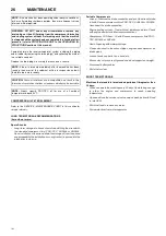
MINIMUM PRESSURE VALVE - WHEN FITTED

NOTE:

 Pressure will always remain in the part of the system between

the minimum pressure valve and the discharge valve after operation
of the auto blowdown valve.

This pressure must be relieved by carefully:

a) Disconnecting any downstream equipment.

b) Opening the discharge valve to atmosphere.

c) (Use hearing protection if necessary).

NOTE: 

Do not press the load button.

NOTE: 

Do not press the load button.

Содержание 7/53

Страница 1: ...ns important safety information and must be made available to personnel who operate and maintain this machine 46673723_en_A_06 15 7 53 OPERATION AND MAINTENANCE MANUAL Original Instruction 7 53 SERIAL...

Страница 2: ......

Страница 3: ...13 2000 14 EC The Noise Emission Directive 14 97 23 EC The Pressure Equipment Directive 15 2009 105 EC The Simple Pressure Vessels Directive 16 97 68 EC The emission of engines for no road mobile mach...

Страница 4: ......

Страница 5: ...separator Hoses Electrical system Battery Pressure system Tyres Tyre Pressure Running gear wheels Brakes Running gear wheel bearings Lubrication Engine lubricating oil Engine lubricating oil specific...

Страница 6: ...ent machine F H R G Fixed height running gear V H R G Variable height running gear bg Bulgarian cs Czech da Danish de German el Greek en English es Spanish et Estonian fi Finnish fr French hu Hungaria...

Страница 7: ...hout notice and without incurring any obligation to make such changes or add such improvements to products sold previously The intended uses of this machine are outlined below and examples of unapprov...

Страница 8: ...G Corrosion risk WARNING Air gas flow or Air discharge WARNING Pressurised vessel WARNING Hot and harmful exhaust gas WARNING Flammable liquid WARNING Maintain correct tyre pressure Refer to the GENER...

Страница 9: ...ir from this machine Do not remove the Operating and Maintenance manual and manual holder from this machine Do not stack Do not operate the machine without the guard being fitted Do not stand on any s...

Страница 10: ...When parking use prop stand handbrake and wheel chocks Compressor oil filling Diesel fuel No open flame Parking brake Rough Service Designation Wet Location Operation Replace any cracked protective sh...

Страница 11: ...DECALS 7 7 53 Engine oil drain...

Страница 12: ...ver operate unit with guards covers or screens removed Keep hands hair clothing tools blow gun tips etc well away from moving parts Compressed air Compressed air can be dangerous if incorrectly handle...

Страница 13: ...e socket control panel in the event of electrical hazards associated with generator operation Use this second control to immediately isolate all electrical power to all sockets then use the key contro...

Страница 14: ...r adjustment of the drawbar To ensure full braking efficiency the front towing eye section must always be set level To ensure full braking efficiency the front towing eye section must always be set le...

Страница 15: ...GENERAL INFORMATION 11 7 53 7 53 FIXED HEIGHT RUNNING GEAR 7 53 VARIABLE HEIGHT RUNNING GEAR...

Страница 16: ...on A B H J O P Q R S T U V W X mm mm mm mm mm mm mm mm mm mm mm mm mm mm 1 7 53 Fixed Height braked 2110 MIN 2127 MAX 3325 MIN 3380 MAX 405 1851 386 904 1290 1220 TBA 940 1430 1205 2 7 53 Variable Hei...

Страница 17: ...When this has been completed the following oils are approved a for ambient temperatures above 23 C 9 F SAE 10W API CF 4 CG 4 Safety data sheets can be obtained on request from your Doosan dealership...

Страница 18: ...and packing materials are discarded Ensure that the correct fork lift truck slots or marked lifting tie down points are used whenever the machine is lifted or transported When selecting the working po...

Страница 19: ...ose restraints whipchecks must be used to prevent hose whipping if a connection fails Whipchecks are to be constructed of woven stainless steel galvanized steel wire rope or chain with aminimum streng...

Страница 20: ...sure gauge D Hourmeter E Warning lamp low engine oil pressure F Warning lamp high airend discharge temperature G Warning lamp dirty IQ filters IQ filters option H Warning lamp High engine coolant temp...

Страница 21: ...e machine has been switched off for reasons of safety then ensure that the machine can be operated safely before re starting Refer to the PRIOR TO STARTING and STARTING THE UNIT instructions earlier i...

Страница 22: ...g kits Warranty does not cover failures attributable to mounting of the compressor package to the carrier base unless it is a Portable Power provided system NOTE The maintenance schedule in this manua...

Страница 23: ...Waterseparator element R Final Fuel Filter R Engine Oil Filter R C Check and act if required T Test D Drain R Replace R WI Replace or when indicated earlier C R Check and replace if required G C Grea...

Страница 24: ...ior C Lubricator Fill C Engine Air inlet shutdown valve C C Check and act if required T Test D Drain R Replace R WI Replace or when indicated earlier C R Check and replace if required G C Grease and c...

Страница 25: ...e tasks which require the machine to be running with safety protection devices disabled or removed all hazards present are known e g pressurised components electrically live components removed panels...

Страница 26: ...ase oil and dirt accumulate on the exterior surfaces of the oil cooler and radiator the efficiency is impaired It is recommended that each month the oil cooler and radiator be cleaned by directing a j...

Страница 27: ...E CHART HOSES All components of the engine cooling air intake system should be checked periodically to keep the engine at peak efficiency At the recommended intervals see the SERVICE MAINTENANCE CHART...

Страница 28: ...es 11 operate smoothly 2 Brake Shoe Adjustment Tighten adjusting screw 12 clockwise until the wheel locks Loosen adjusting screw 12 anti clockwise approx turn until the wheel can be moved freely Sligh...

Страница 29: ...tensioned Excessive operation of the handbrake lever which may have been caused by worn brake linings must not be corrected by re adjusting shortening the brake linkage 7 Re adjustment The handbrake l...

Страница 30: ...es Loosen tension on belts fan airend etc Block axles so tyres are off ground and do not support any weight Disconnect battery cables Drain fuel system SHORT TERM STORAGE Machines that stand idle for...

Страница 31: ...service valve is fully open Refer to the GENERAL INFORMATION section of this manual Adjust the service valve on the outside of the machine to maintain 7 bar without the throttle arm moving from the fu...

Страница 32: ...ssis 54 58 73 78 Euro Loc adaptor to separator tank 58 67 78 91 Exhaust flange to manifold 17 21 23 28 Fan guard 9 11 12 15 Fan to hub 12 15 16 20 Lifting bail bracket to engine 29 35 39 47 Oil pipe 1...

Страница 33: ...rranty section for details or contact your Portable Power representative Design Operating Pressure Ambient Temperature Specification 100 psi to 300 psi 7 bar to 21 bar 10 F to 125 F 23 C to 52 C Prefe...

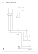
Страница 34: ...30 ELECTRICAL SYSTEM 7 53 7 53...

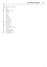
Страница 35: ...A G1 Alternator H1 Hourmeter K1 Crank relay K2 Engine heater relay K3 Contactor Option PB1 Warm up button PS1 Oil pressure switch P1 Mini controller SV1 Fuel solenoid SV2 Warm up solenoid SV3 Generato...

Страница 36: ...32 ELECTRICAL SYSTEM 7 53 7 53...

Страница 37: ...ECTRICAL SYSTEM 33 7 53 KEY PS2 IQ restriction switch P2 Mini controller S3 Low fuel switch 1 Airend temperature 2 Engine oil pressure 3 Engine temperature 4 Low fuel 5 No charge 6 IQ filter restricti...

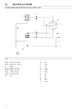
Страница 38: ...EY IL LH Indicator light left hand IL RH Indicator light right hand FL Fog light SL LH Stop light left hand SL RH Stop light right hand TL LH Tail light left hand TL RH Tail light right hand PL Plug B...

Страница 39: ...OPTION KEY IL LH Indicator light left hand IL RH Indicator light right hand FL Fog light RL Reverse light SL LH Stop light left hand SL RH Stop light right hand TL LH Tail light left hand TL RH Tail...

Страница 40: ...53 KEY 1 Air discharge 2 Sonic orifice restricts flow 3 Pressure gauge 4 Separator tank 5 Safety valve 6 Compressor 7 Engine 8 Oil cooler 9 Oil filter 10 Thermostatic valve Where fitted 11 Separator f...

Страница 41: ...oil temperature Check the compressor oil level and oil cooler Check the fan drive Water present in fuel system Check the water separator and clean if required Faulty relay Check the relay in the holde...

Страница 42: ...t setting of the regulator Adjust the regulator Faulty regulator Replace the regulator Inlet valve set incorrectly Refer to SPEED AND PRESSURE REGULATION ADJUSTMENT in the MAINTENANCE section of this...

Страница 43: ...ate in the aftercooler to drain This is to prevent cooler damage at freezing temperatures These drains are plugged through the compressor frame and will expel condensation to atmosphere Should site co...

Страница 44: ...40 OPTIONS 7 53 WATER SEPARATOR MAINTENANCE FIGURE 4 FIGURE 5 FIGURE 1 FIGURE 2 FIGURE 3...

Страница 45: ...r levels causing overheating reduced engine life and reduced airend life CAUTION Excessively restricted filter elements may cause an increase in the amount of aerosol water and oil carryover which cou...

Страница 46: ...8 5 mins off load Air in temp 35 40 C 50 mins hr 0 8 10 mins off load Air in temp 40 C 45 mins hr 0 8 15 mins off load Socket outlets 110V 1ph 230V 1ph 1 x 32 amperes 2 x 16 amperes 230V 3ph 1 x 16 a...

Страница 47: ...dure which has been issued by supervisory personnel and that it is understood by all persons concerned with the operation of the generator Ensure that the safety procedure to be applied is based on th...

Страница 48: ...G THE UNIT instructions earlier in this section before re starting the machine DECOMMISSIONING When the machine is to be permanently decommissioned or dismantled it is important to ensure that all haz...

Страница 49: ...ring The No load voltage falls when a load is applied Check the capacitors and associated wiring Loss of residual magnetic field Refer to Mecc Alte maintenance manual No output Output winding s damage...

Страница 50: ...ove the generator KEY CB1 RCD Circuit breaker 63A CB2 Circuit breaker 32A CB3 Circuit breaker 16A CB4 Circuit breaker 16A F1 Fuse 1A F2 Fuse 1A G Alternator 1 phase GND Earth stud KM1 Contactor P1 Con...

Страница 51: ...machine above the generator KEY CB1 RCD Circuit breaker 32A CB2 Circuit breaker 16A CB3 Circuit breaker 16A F1 Fuse 1A F2 Fuse 2A G Alternator 1 phase GND Earth stud KM1 Contactor P1 Connector voltme...

Страница 52: ...he machine above the generator KEY CB1 RCD Circuit breaker 10A CB2 Circuit breaker 10A CB3 Circuit breaker 10A F1 Fuse 1A F2 Fuse 1A G Alternator 3 phase GND Earth stud KM1 Contactor P1 Connector volt...

Страница 53: ...own occurs 6 Repeat the above steps 2 to 5 until the first setting at which the engine does not shut down at high idle speed Then either A Use the results of shut down speed versus adjuster setting as...

Страница 54: ...hake out Also by shaking check for any loose internal baffles Six Monthly or 1500 hours operation whichever is sooner Examine the exhaust discharge in darkness whilst repeatedly loading and accelerati...

Страница 55: ...TO USE PARTS LIST a Turn to Parts List b Locate the area or system of the compressor in which the desired part is used and find illustration page number c Locate the desired part on the illustration b...

Страница 56: ...ive and the total liability of the Company with respect to this order whether based on contract warranty negligence indemnity strict liability or otherwise shall not exceed the purchase price of the p...

Страница 57: ...n regarding your local distributor U S Latin America or Asia Pacific please contact Office hours Monday to Friday 8 00 a m to 5 30 p m EST Facility Telephone Fax Doosan Portable Power EMEA Aftermarket...

Страница 58: ......

Страница 59: ......

Страница 60: ......

Отзывы: