installation manual sHaF t-30
4
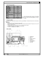
4. Safety instructions
it is important that you read all the following instruction:
•
the door operator should be installed and put into operation by qualified personnel. otherwise, serious personal injury or property damage
•
may occur.
open and close the door manually, make sure the door can be moved smoothly.
•
the door must be equipped with balance springs, otherwise the operator will be damaged. Before installation of the door operator, the
•
door should be carefully checked for being kept well balance. the door must be in good working order.
it is recommended to install limit devices on door tracks to prevent the door from sliding out of the tracks.
•
the operator motor may only be disengaged with the door closed. this must be carried out by specialist personnel for maintenance
•
purpose only.
Keep button switch away from children, to prevent the door operator from being activated involuntarily.
•
the operator should be switched off before repairing it or opening its cover.
•
When opening or closing the door, do not attempt to walk or drive through the door.
•
the door should only be operated when it can be observed to avoid accidents.
•
Do not pull the hand chain during opening or closing the door.
•
WARNING:
important safety instructions. it is important for the safety of persons to follow all instructions. save these instructions.
Fre quently examine the installation, in particular check cables, springs and mountings for signs of wear, damage or imbalance.
Do not use if repair or adjustment is needed since a fault in the installation or an incorrectly balanced door may cause injury.
WARNING:
important safety instructions. Follow all instructions since incorrect installation can lead to severe injury.
WARNING:
permanently fix the labels warning against entrapment in a prominent place or near any fixed controls.
Frequently examine the installation, in particular check cables, springs and mountings for signs of wear, damage or imbalance. Do not use
•
if repair or adjustment is needed since a fault in the installation or an incorrectly balanced door may cause injury;
before installing the drive, remove all unnecessary ropes or chains and disable any equipment, such as locks, not needed for powered
•
operation;
install the actuating member for the manual release at a height less than 1,8 m;
•
if removable, the actuating member should be stored in direct vicinity of the door.
•
install any fixed control at a height of at least 1,5 m and within sight of the door but away from moving parts
•
it is not required to specify a minimum height for keyoperated switches.
•
the fixed electric wiring shall have builtin disconnectors according to the wiring rules
•
good condition of system units and safety devices order shall be checked each half year
•
the motor is used for mounting at the height not more 2.5 meters. to mount the motor at the height more than 2.5 meters it is necessary
•
to observe the rules of working at the height.
if the drive is not to be used with doors having openings exceeding 10 mm in diameter or having edges or protruding parts a person could
•
grip or stand on.
5. Installation
Before installing, make sure the door is in good working order. We advise to install the operator as follow see ‘direct installation’ section or
‘indirect installation’ section:
(1) Direct installation (standard accessories see page8 packing list)
screw the wall bracket (lshaped iron fitting) onto the wall. You may install the wall bracket to left side or right side of operator.
Remove the plastic housing, rotate release handle 180°anticlockwise.
slot the 1st spacer ring onto the door shaft.
slot the door operator onto the door shaft (ensure correct position of the key) and screw onto the wall bracket.
slot the 2nd spacer ring onto the door shaft and push against the door operator. Push the 1st spacer ring against the door operator and fix
both rings.
You also can install the door operator as shown in Fig.3.
Drill four holes on the shaft bearing bracket.
Remove the plastic housing, rotate release handle 180°anticlockwise.
Direct attach the door operator onto the door shaft end and screw onto the shaft bearing bracket, ensure the correct position of the key.
adjust the position of the operator and ensure the hand chain hangs vertically.
slot the spacer ring onto the shaft and fix ring with screw.
(2) indirect installation (You can purchase the optional accessories from our company.)
4
safETy INsTrUcTIONs
Содержание SHAFT-30
Страница 1: ...installation manual SHAFT 30 ...


