background image


VPRS-430 OPERATION MANUAL 

Issue : 2009.03 

ED : 1


 VPRS-430 OPERATION MANUAL                                                         13 /30  


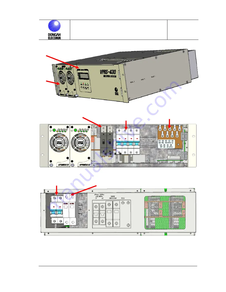
(Front Panel Closed View) 


(Front Panel Open View) 


(Rear  Panel Open View) 


Figure 1.  Exterior View of VPRS-430 


Rectifier 

Module Part 

Rectifier 

Controler Part 

Battery C/B(#1,#2) 

Output  +27V C/B(L1~L4) 

Output  GND 

AC INPUT C/B9(16A)  SURGE PROTECTOR 

Содержание VPRS-430

Страница 1: ...220V AC 1Phase Input 54 5VDC Output 30Amps per Shelf 15Amps per Module VPRS 430 POWER SUPPLY SYSTEM OPERATION MANUAL ...

Страница 2: ... 1 2 2 Surge Voltage of Power Cable 11 1 2 3 Leaked Current 11 1 3 ENVIRONMENTAL CHARACTERISTICS 11 1 3 1 Operating Temperature Humidity 11 1 3 2 Storage Temperature Humidity 11 1 4 PHYSICAL SPECIFICATIONS 11 1 4 1 Dimension 11 1 4 2 Weight 11 2 RECTIFIER SYSTEM CONFIGURATION 12 2 1 CONFIGURATION 12 2 2 FRONT VIEW 12 2 3 FUNCTIONS 12 2 4 RECTIFIER SYSTEM BLOCK DIAGRAM 14 3 INITIALIZATION CHECK POI...

Страница 3: ...VR 19 5 CONTROL PANEL OPERATION 20 5 1 DISPLAY 20 5 2 CONTROL PANEL FUNCTIONS 20 5 3 CONTROL PANEL OPERATION 21 6 MANUAL BATTERY DISCONNECT 21 7 RECTIFIER SYSTEM OPERATION STOP OPERATION 22 7 1 RECTIFIER SYSTEM OPERATION 22 7 2 RECTIFIER SYSTEM STOPPING LOCAL 22 7 3 BATTERY TEMPERATURE COMPENSATION BTC MODE IN TEMP ON 22 7 4 OUTPUT VOLTAGE FL CHAGE MODE SELECT TEMP OFF 23 7 5 OUTPUT VOLTAGE EQ CHA...

Страница 4: ... 1 8 Battery charge start current setting 26 8 1 9 Temp ON OFF setting 26 8 1 10 Battery charge mode setting 26 8 1 11 Battery emergency voltage setting 26 8 1 12 Alarm History Clerar 26 8 1 13 Alarm Sound Setting 26 8 2 CONTROL PANEL MEASUREMENT 26 8 2 1 Input voltage measurement 26 8 2 2 Output voltage current measurement 26 8 2 3 Battery charge discharge current measurement 26 8 2 4 Current mea...

Страница 5: ...Safety Tips For Your Safe Operation Before starting the installation operation test and repair work please read carefully al of the directions specified in this manual for your safe operation of the system This product has been manufactured under strict quality management If there are any potential damages to human life or assets please contact Dongahelecomm This document deals with safety directi...

Страница 6: ...s Make sure that the delivered product is the same one that you ordered Check first the quantity of the delivered articles as specified in the enclosed sheet Thene make sure that there are any missing parts deformation damage peeled out paints unscrews or damage of cables Directions in Storage Do not put this product package in a place where water or rain drops there are any harmful gas or liquids...

Страница 7: ...grounding wire ports It may cause an electric shock or short circuit Pay attention not to reverse polarity of signaling cables and detection cables when connected It may cause a fire Do not leave alien materials such as sheathes of electric wires screws and so on inside the product It may cause an electric shock or fire DC output is connected to the battery before the system starts to be driven Pa...

Страница 8: ...hould be used at 60V or lower of input voltage and 0 5A or lower of circuit current Before you take apart or insert the RS232C and RS485 ports of the control module turn off the control module switch When you take apart or insert the rectifier unit from to the rectifier system turn off the rectifier unit switch Rectifier unit should be inserted and taken apart in line with the guide rail of the re...

Страница 9: ...ience should repair this product Violating this direction may cause an electrtic shock or fire As AC input and DC voltage are applied take particular attention not to have electric shock or short circuit when the system is tested or repaired Even when the system is turned on while commercial power is failed AC input may be fed to the system Take particular attention to test and repair work of the ...

Страница 10: ...at 10 100 load 1 1 2 Output Characteristics 1 Rated output voltage 54 5V 0 545V 2 Operating voltage 40 0V 59 0V 3 Output current max 10A 15A 2 Modules N 1 4 Output distribution circuit Refer to Table 1 Table 1 Output Distribution NO Output Port Class Cap Volt Description 1 L1 2 DC 10A 2PORT 54 5V Load voltage supply 1 2 2 L3 4 DC 6A 2PORT 54 5V Load voltage supply 3 4 3 BATTERY 1 DC 20A 1PORT 1 Ba...

Страница 11: ...ART 15 SUBPART B CLASS A 450kHz f 1 6MHz 1mV 60dB or lower 1 6MHz f 30MHz 3mV 69 5dB or lower 1 2 2 Surge Voltage of Power Cable Î Voltage 6kV 1 2 50 Current 3kA 8 20 1 2 3 Leaked Current Î 10mA or lower 1 3 Environmental Characteristics 1 3 1 Operating Temperature Humidity 10 55 10 95 1 3 2 Storage Temperature Humidity 40 80 5 95 1 4 Physical Specifications 1 4 1 Dimension VPRS 430 Rectifier Shel...

Страница 12: ...ply and 2 circuit for battery connection This rectifier has been designed to charge the battery with positive ground and can be used for the system without any battery installed or connected Rectifier capacity can easily be built up by adding modules 2 2 Front View Figures 1 shows the exterior view of the rectifier 2 3 Functions Table 2 Rectifier System Functions Classification No of Modules Funct...

Страница 13: ... OPERATION MANUAL 13 30 Front Panel Closed View Front Panel Open View Rear Panel Open View Figure 1 Exterior View of VPRS 430 Rectifier Module Part Rectifier Controler Part Battery C B 1 2 Output 27V C B L1 L4 Output GND AC INPUT C B9 16A SURGE PROTECTOR ...

Страница 14: ...VPRS 430 OPERATION MANUAL Issue 2009 03 ED 1 VPRS 430 OPERATION MANUAL 14 30 2 4 Rectifier System Block Diagram Figure 2 VPRS 430 Block Diagram ...

Страница 15: ...usbar 8 Check if the I O cable has been correctly connected 9 Check if the rectifier modules have been fully inserted Once all of the cabling and installation procedures are finished initialize the system and carry out the function test in the following order 1 Check if all of the power switches have been turned off and check polarity and cable connection status of batteries using DVM 2 Check if t...

Страница 16: ...le the rectifier is in operation 3 2 2 Rectifier Module Deletion Turn off the power switch of the module Then loosen the captive screws on it Pull out the module seizing the handle on it Before starting the action wait for about 1 minute until the LED is turned off Caution Turn off power switch when taking apart a module 3 3 Normal Operation Default setting of the output voltage of this rectifier ...

Страница 17: ...orrective Measures If FAIL LED is turned on while the rectifier system is driven that means the rectifier system is abnormal in operation Alarm status is displayed on the LCD window of the control panel Check the alarm status and take proper actions Figure 4 Control Panel Front Status Indication Error Normal LED ON Error Message Display Fail LED ON RED ...

Страница 18: ...normally connected B NFB Check if battery 1 2 C B OFF Position OCA Check the input voltage and check if the output is open See How to Operate Control Unit If the listed problem is not solved after the recommended actions are taken or if other problems occur contact A S center 4 Rectifier Module Configuration 4 1 Standby Operating Switch During the operation the module should be in Operating Mode I...

Страница 19: ...utput OV protection circuit driving When the module is shut down due to internal high temperature protection circuit driving When the voltage falls below UV limit due to current limit circuit driving When internal fan is failed When the module is shut down due to an external signal Green yellow and red LEDs are blinking When output is not made due to other problems or when the voltage falls below ...

Страница 20: ... OPERATION MANUAL 20 30 Figure 5 Front View of Rectifier Module 5 Control Panel Operation 5 1 DISPLAY Figure 6 Control Panel Front View 5 2 Control Panel Functions See Control Panel Operation Manual Table 5 Adjustments Menu Defaults Standby Operate Button ...

Страница 21: ...attery Charge Current 10A 200A 50A Battery Charge End Current 2A 100A 5A Temp Mode ON OFF ON Battery Charge Slect Auto Manual FL MODE EQ MODE Auto Battery Emergency Voltage 42 0V 48 0V 44 0V 5 3 Control Panel Operation See Control Panel Operation Manual 6 Manual Battery Disconnect Manual BATTERY DISCONNECT switch C B Circuit Breker type located at the rear side of the front panel When the C B is i...

Страница 22: ...system name displayed at the LCD of the control unit matches the actual rectifier Shelf installed Check if the STATUS LED indicates normal 7 2 Rectifier System Stopping LOCAL Turn off the switch of each rectifier unit Yellow LED on each rectifier unit is turned on Turn off the main breaker at the distribution panel Turn off the power switch of the control unit 7 3 Battery Temperature Compensation ...

Страница 23: ... p Vo u t 1 0 A c tu a l T e m p e ra tu re C o rre c te d Vo lta g e 2 2 0 V C e ll 2 2 4 V C e ll 2 3 0 V C e ll 2 3 5 V C e ll 3 2 9 0 F o r a b o v e 2 5 7 7 F 1 5 5 9 F 5 4 0 F o r b e lo w Figure 8 BTC FL MODE EQ Charge Mode 5 6 4 V 5 2 8 V 0 2 5 5 2 T e m p Vo u t 1 0 A c tu a l T e m p e ra tu re C o rre c te d Vo lta g e 2 2 0 V C e ll 2 2 4 V C e ll 2 3 0 V C e ll 2 3 5 V C e ll 5 2 1 2 ...

Страница 24: ...er is initialized it will operate up to 32 hours at AUTO EQ mode automatically That is because the battery may have been discharged in the storage process If AUTO EQ is selected EQ charge is started and auto EQ mode is maintained until 10 minutes pass after current falls below battery end current limit EQ state is maintained for up to 32 hours after EQ charge gets started If EQ charge period excee...

Страница 25: ... the switch again to ON manually 7 7 Battery Charge Current Limitation This function enables user to set ON or OFF Default is OFF In that case the maximum value of charge current equals the output current limit of rectifier which means max current limit of the installed rectifier modules See Table 5 7 8 Control Panel Power Drop If power of the rectifier system falls below 42 0V due to commercial p...

Страница 26: ...1 Battery emergency voltage setting 8 1 12 Alarm History Clerar 8 1 13 Alarm Sound Setting See Control Panel Operation Manual 8 2 Control Panel Measurement Control panel displays various measurements related with the operation of the rectifier system at the front LCD window and the meter window and displays alarm and operation status indications 8 2 1 Input voltage measurement 8 2 2 Output voltage...

Страница 27: ...ay cause electric shock As battery voltage is fed to the system safety measures should be taken to repair and maintain the system As the battery generate a large amount of DC current worker should take off watch ring or other metallic accessories 9 2 Periodic Inspection To guarantee effective operation of the system periodic inspection is required Periodic inspection should be carried out one time...

Страница 28: ...re of each rectifier unit For details see Control Panel Operation Manual 6 If total current does not increase after a new module is inserted check if the module has any problem on it and check the ID setting of the rectifier module 7 Check if the rectififer generates any alarm or has any errors on it Figure 10 Rectifier Module Insert 10 Problem Solving Fault Fixing Repairing or problem fixing of t...

Страница 29: ...stribution panel fuse and NFB 10 3 Order of Replacement 10 3 1Replacement of Rectifier Module VPRM5415 1 When a rectifier module is replaced alarm will be driven Turn off the rectifier module from the control panel or notify this fact to the person in charge 2 Set the switch of the rectifier module to STB 3 Turn the captive screw of the module counter clockwise Then take out the module from the sh...

Страница 30: ...ector of the separated front panel and power switch connector from the rectifier module 6 Loosen the 4 nuts fixing the front panel to the fan 7 Separate the fan front panel and fan grill 8 Replace the fan and then take the opposite direction from 7 to 4 For fan assembly make the arrow mark on the fan facing inner side of the module Fan connector cable should face downward and then assemble it 9 Ch...

Страница 31: ...er system rear Pull out with a hand the part to be replaced from the SURGE PROTECTOR at the rear Insert the new part in the opposite order Caution As power is directly applied to the surge protector while input power is fed particular care must be paid 11 Acronyms GSM Global Standard System for Mobile NFB No Fuse Breaker C B Circuit Breaker S W Switch RMS Root Mean Square LVD LOW VOLTAGE DISCONNEC...

Страница 32: ...VPRS 430 OPERATION MANUAL Issue 2009 03 ED 1 VPRS 430 OPERATION MANUAL 32 30 ...

Страница 33: ...R OPERATION MANUAL 2009 Dongahelecomm Corp All rights reserved Information in this document is proprietary to dongahelecomm No information contained here may be copied translated transcribed or duplicated by any form without the prior written consent of Dongahelecomm http www Dongahelecomm co kr ...

Отзывы: