


Written Date
2010.05.30
Document No.
Change code
0
File/Reference
Operation Manual.DOC
Page
(5/21)
DONGAH ELECOMM R&D CENTER
All rights are reserved.
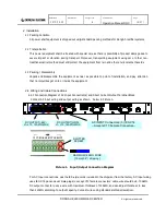
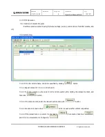
2.4.2 TCP/IP Connection Diagram
Connect as shown below in Picture 2.
Picture 2. TCP/IP Connection Diagram
TCP/IP PORT is located at the left of the shelf, on the front panel of the DIRC-4 control module and it is
used by attaching a standard Ethernet cable to the TCP/IP port.
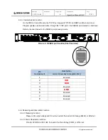
3. Rectifier System: Shelf Components and Functions
A full Rectifier System consists of (1) 1U Shelf, (1) Control Module, (3) Rectifier Modules, and (1) Distribution
Panel. Picture 3 diagrams a 19" Shelf with the DIRC-4 Control Module, (3) DIRS-440 Rectifier Modules,
Picture 3. DIRS-4110 Shelf Diagram (Front)
TCP/IP Port
CONTROL MODULE
RECTIFIER MODULES
DISTRIBUTION PANEL
and the Distribution Panel with 10 GMT Fuse locations.


