


Written Date
2010.05.30
Document No.
Change code
0
File/Reference
Operation Manual.DOC
Page
(10/21)
DONGAH ELECOMM R&D CENTER
All rights are reserved.
5.2 Rectifier System Block Diagram
5.3 Initial Inspection and Power-Up
5.3.1 Preliminary Inspection
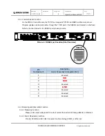
5.3.1.1 Disconnect the AC Input power. Visually inspect the GMT fuses to ensure correct ratings and
proper insertion into the fuse block. Ensure the Control Module and Rectifiers are fully inserted
and locked into the Shelf.
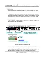
5.3.1.2 Visually inspect the input and output wiring for clean, secure connections. Ensure shelf mounting
brackets are tight and secure.
5.3.2 Rectifier System Power-Up
5.3.2.1 When preliminary inspection is complete, confirm the AC input voltage is within specifications
that all output cables are connected properly between the Rectifier System outputs and the inputs
to the customer's system (loads).
5.3.2.2 Power On
a. Apply AC Input power to shelf.
b. Confirm that the Rectifier Modules (DRM-440) operate normally by observing Green LED is lit
steadily on the front panel of each module.
DIRS-4110 BLOCK DIAGRAM
DC
Outputs
Input
AC
c. Confirm that the Control Module (DIRC-4) is monitoring, controlling, and communicating within the shelf
properly by observing GREEN Led is lit steadily on the front of the Control Module.
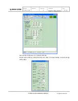
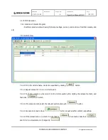
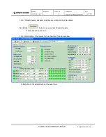
d. Set up and run Shelf software to ensure proper operation and no alarms are present.


