background image

PROGRAMMING THE PRINTER

74

77144  Issue 8 August 2009

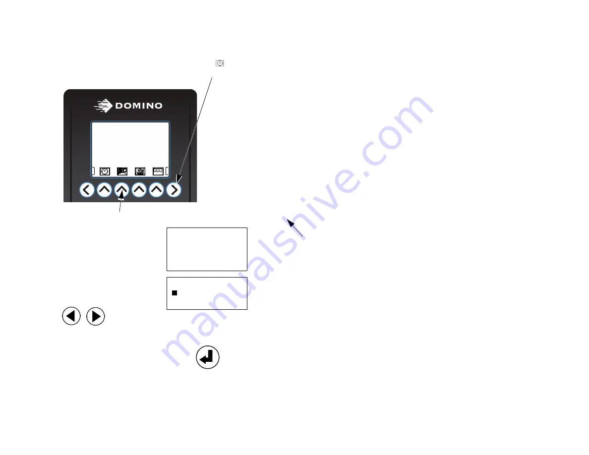
Amend the clock function, as follows:

(1) Scroll through the menu bar functions and select the 

set clock


icon.


(2) The Clock Options submenu is displayed.

Select the time option by using the up down
cursor keys and press 

enter

.

(3) A flashing cursor block at the beginning of

the hours format can be moved left or right
by pressing the cursor arrows on the key pad.


(4) To re-adjust any of the values, place the

cursor over the character to be adjusted and
overtype the new value, when all changes are
completed press 

enter

.

Note:

Values that are outside the parameters of the 24 hour clock or calendar month,
are not accepted.

Press the corresponding key to select the function

PRINTING MESSAGE1

NORMAL PRINT

INK STATUS OK

Press right directional key until the menu bar starts to scroll

1 2 3

CLOCK OPTIONS

> FIRST WOY

TIME

HR:MI DT/MO/YR D

5 : 28  10/12/99 5

Flashing block cursor can scroll 

across time/date/day format 

enabling operator to edit the 

clock time.

Содержание C1000 plus

Страница 1: ...C Seriesplus Printer Operation and Maintenance Manual ...

Страница 2: ...2 77144 Issue 8 August 2009 THIS PAGE INTENTIONALLY BLANK ...

Страница 3: ...Drive Cambridge CB3 8TU Gurnee IL 60031 Tel 44 1954 782551 Tel 1 847 244 2501 Fax 44 1954 782874 Fax 1 847 244 1421 All rights reserved No part of this publication may be reproduced stored on a retrieval system or transmitted in any form or by any means electronic mechanical photocopying recording or otherwise without the prior permission of Domino Printing Sciences plc Domino Printing Sciences pl...

Страница 4: ...the requirements of the following documents EN 61000 6 4 2007 Electromagnetic Compatibility EMC Generic Standards Emission standard for industrial environments EN 61000 6 2 2007 Electromagnetic Compatibility EMC Generic Standards Immunity Standard for industrial environments EN 55022 1 1998 Class A Electromagnetic Compatibility Radiated EN 60950 2000 Safety of Information Technology Equipment 2006...

Страница 5: ...d Remote 13 Control Unit 13 Base 14 Data Input 14 Environment 14 Base Unit Connectors MHB 15 BASIC OPERATIONS 16 Base Unit Mounting 23 Dual Mounting Bracket 25 Control Unit Head Mounting 26 Control Unit Height Adjustment 27 Rotating the Remote Head 90 C3000X and C1000X Only 28 Printing at Angles C6000I Only 30 PRINT HEAD SETUP C6000v ONLY 32 Setup Procedure 32 Printing at Angles C3000X and C1000X ...

Страница 6: ... Driven 52 Control Unit Keypad Layout 53 Basic Interface Controls 55 Functions and Menus 56 Keypad Functions 57 Function Keys C6000 MF Only 58 LCD Screen Icons C6000 MF Only 58 LCD Screen Icons 60 Interface Map 63 Setting a Print Job 65 Printing a Default Test Message 68 Printing a Saved Message 69 Deleting a Saved Message 71 PROGRAMMING THE PRINTER 72 Selecting a Language 72 Setting the Clock 73 ...

Страница 7: ...ellite Mode 85 Switches 85 Shaft Encoder 85 Shaft Encoder Test 86 Screen Saver 86 Acknowledgement 86 Record Change 86 Bottle Out 86 Extra Port 87 Retrieve Mode 87 Sensor 87 Auto Prime 87 IP Settings 87 FORMATTING MESSAGES 88 Creating a Message 88 Edit Which Message Sub Menus 90 Select Alternative Font 91 Entering Text 92 Message Layout 97 Adding Spaces 99 Saving a Message 100 Message Attributes 10...

Страница 8: ...DJUSTING PARAMETERS 120 Message Parameters 120 MAINTENANCE 129 Routine Maintenance 129 Daily Maintenance 130 Changing the Ink Collection Sponge 131 Every 6 Months 133 Cleaning the Nozzle Plate 135 C6000v Head Cleaning 135 Relocating the Unit 136 C1000X C3000X PRINT HEAD POSITIONING 137 DIMENSION DRAWINGS 139 TROUBLESHOOTING 159 OPERATOR NOTES 164 Message Notes 164 INDEX 167 ...

Страница 9: ...harge precautions must be taken to prevent this form of ignition occurring Please refer to the Domino Safety Data Sheet SDS for further details Maintenance WARNINGS 1 When performing any maintenance tasks that involve the disassembly of any part ensure the mains power is removed 2 Ink contact with the eyes must be avoided therefore eye protection must be worn whenever there is risk of ink splashin...

Страница 10: ...ilable taking care not to allow the water to run into the unaffected eye Medical aid must be obtained immediately Skin contact Remove contaminated clothing Wash skin with water If symptoms develop obtain medical attention Ingestion Wash out mouth with water and give 200 300ml of water to drink Do not induce vomiting Obtain medical advice Inhalation Remove patient from exposure keep warm and at res...

Страница 11: ...mum of 8mm C3000 X 35mm to a minimum of 4mm and C1000 X 17mm to a minimum of 2mm and is editable with various formats The X designates that the printer has a remote print head attached to the control unit via a conduit The i designates a remote inclined print head also attached to the control unit via a conduit this can be used where a conveyor is not horizontal Unless otherwise stated in this man...

Страница 12: ...INTRODUCTION 12 77144 Issue 8 August 2009 THIS PAGE INTENTIONALLY BLANK ...

Страница 13: ... 39 5mm x 71 5mm x 65mm 256 dot 59 5mm x 90mm x 90mm 500 dot inclined 79mm x 114mm x 187mm 500 dot 79mm x 170mm x 114 Conduit Length 128 256 dot 1 0m 500 dot only 1 5m Standard Finish Grained 304 Stainless Steel Dimensions width x length x height 128 dot 113mm x 295mm x 125mm 256 dot 113mm x 295mm x 146mm 500 dot 113mm x 370mm x 160mm Control Panel Material Polyester Membrane Touch Panel ...

Страница 14: ...s Steel Dimensions width x length x height 200ml 152mm x 360mm x 108mm 2 litre 228mm x 507mm x 139mm Dimensions incl bracket width x height x depth 289mm x 520mm x 252mm Weight no fluids 16 3kg Interface Rate RS232 300 115200 Baud Software Configurable TCP IP 10BaseT Temperature Range working 10ºC to 40ºC 50ºF to 104ºF Humidity 10 90 RH Electrical Supply Single Phase 90 240V 50 60 Hz ...

Страница 15: ...D Bottle Empty Alarm Connector DIN 5 way 240 Ink Out Alarm Connector DIN 5 way 240 Base and Head Connections Product Detector Connector DIN 5 way 180 TCP IP Connector RJ45 Bottle Out Alarm Connector DIN 5 way 240 2 litre base only Shaft Encoder Connector via Accessory Connection Box ACB DIN 4 way Shaft Encoder Input PNP RS232 Connector via ACB 9 way D Ink Out Alarm Connector via ACB DIN 5way 240 P...

Страница 16: ...BASIC OPERATIONS 16 77144 Issue 8 August 2009 BASIC OPERATIONS Door Latch Power Switch Multi head Base Unit Ink Bottle behind door Mounting Bracket ...

Страница 17: ...BASIC OPERATIONS 77144 Issue 8 August 2009 17 2 Litre Base Unit ...

Страница 18: ...BASIC OPERATIONS 18 77144 Issue 8 August 2009 200ml Base Unit ...

Страница 19: ...RATIONS 77144 Issue 8 August 2009 19 Alphanumeric keypad LCD display Control unit Control unit power cable C6000 i Control Unit C6000i Control Unit and Print Head Conduit Control unit Print head Product Detector ...

Страница 20: ...BASIC OPERATIONS 20 77144 Issue 8 August 2009 Keypad LCD display Control unit Control unit power cable C6000MF Control Unit Product Detector ...

Страница 21: ...ASIC OPERATIONS 77144 Issue 8 August 2009 21 LCD display Control unit Control unit power cable C3000 X Control Unit C3000X Control Unit and Print Head Conduit Print head Control unit Alphanumeric keypad ...

Страница 22: ...RATIONS 22 77144 Issue 8 August 2009 Alphanumeric keypad LCD display Control unit Control unit power cable C1000 X Control Unit C1000X Control Unit and Print Head Conduit Print Head Control unit Product Detector ...

Страница 23: ...BASIC OPERATIONS 77144 Issue 8 August 2009 23 BASE UNIT MOUNTING The base unit and control units must be mounted either on a stand or onto the conveyor Stand Multi head Base Stand ...

Страница 24: ...BASIC OPERATIONS 24 77144 Issue 8 August 2009 Conveyor ...

Страница 25: ...ASIC OPERATIONS 77144 Issue 8 August 2009 25 DUAL MOUNTING BRACKET Domino can supply a mounting bracket to enable two print heads to be mounted next to each other on the stand Dual Mounting Bracket Stand ...

Страница 26: ...ly moving the unit s slide bar over the loosened clamping plate Ensure that the unit is well supported during this operation 3 Ensure the front of the unit is facing the conveyor belt as shown To dismount the unit move the slide bar back off the loosened clamping plate ensuring that all connections to the control unit are unplugged 4 When the control unit has been moved to the required position ti...

Страница 27: ...ved for clarity 2 Tighten the fixing knob on the front of the vertical column so that it is holding the vertical mounting post securely in place CAUTION The C6000i print head and control unit must be adjusted to the same height bases and must be kept in the same environment Refer to page 30 for printing at angles 3 To Adjust the C6000i print head slacken the fixing knob and adjust to the required ...

Страница 28: ... of the bracket arm the position of the message can be placed accurately on the print surface 2 Before setting the print the head must be rotated The pivot point of the head will need switching as follows release the bracket screws on either side of the head ensure that the head is held securely and the ship cap is attached 3 Whilst holding the head gently rotate it to the position indicated 4 The...

Страница 29: ...o not over tighten 7 The sensor must also be inverted by slackening the bottom left screw on the sensor bracket and pushing the sensor up so that it is facing down ensuring that the sensor is not triggered by the conveyor 8 The remote head mounting plate must be removed and turned over to compensate for the drop in height due to the new pivot point The mounting plate has a bend on one side that in...

Страница 30: ... head should be mounted on either side of the mounting post as follows Note Before repositioning the mounting brackets ensure the ship cap has been fitted and the vent valve is shut Ensure that the conduit does not become twisted whilst the print head is removed from its mounting 1 Remove the bracket and print head from the mounting post then remove the bracket from the print head Take care to ret...

Страница 31: ...eight as the bottom face of the controller ii Ensure that the print head angle has not exceeded 25º iii If the print head is still weeping it is recommended to lower the controller slightly whilst observing the print until the weeping around the lower dot position has stopped b If any dots are missing from the message particularly at the top it may suggest that the controller is positioned too low...

Страница 32: ...table ink bottle in the base and set the head to the correct height this is 40mm 5mm between the bottom of the unit and the face of the print head Let the unit top up with ink so that it displays ink ok 2 With the ink line disconnected prime heavily until the unit displays ink low Turn the unit off then lift the head cover to close the AR 03 valve 3 Turn the unit back on It will display ink low Pl...

Страница 33: ...les a Weeping If the head is weeping then ensure that the AR 03 is open and that all air has been removed by priming the unit If weeping continues then raise the print head remembering that the maximum height for the face of the print head should be 45mm from the bottom of the unit b Missing channels If a channel is missing on the test print prime the unit and if the problem persists lower the pri...

Страница 34: ...wer pivot point is used the bracket mounting plate must be turned over to compensate for the height difference between the two pivot points The picture shows the different bracket orientations 3 Turn the mounting plate in the direction indicated to correspond with one of the orientations outlined above this will depend on the pivot point chosen Align the holes then mount the control unit and the r...

Страница 35: ...ls the distance between box and print head and also corrects the misalignment of boxes that have moved out of the correct printing path The box guide should only be used in conjunction with conveyor guide rails For installation instructions on this box guide refer to your local Domino office Instructions for changing the ink collection sponge are on page 131 Box guide rail Buffer plate Box Guide I...

Страница 36: ...re than 24 hours Fit the ship cap to the print head as follows 1 Align the ship cap screws with the holes either side of nozzle plate on the front of the control unit and tighten the screws 2 Screws should be tightened to the following torque C1000 and C1000X 0 34 N m C3000 and C3000X 0 68 N m C6000 C6000MF C6000v and C6000i 0 34 N m 3 Remove the ship cap before re starting the unit Ship cap attac...

Страница 37: ...require releasing prior to initial power up There is also a vent in a 2L base that needs to be released For the vent s on the header tank 1 Using a screwdriver remove the four screws securing the control unit cover 2 Carefully raise the control unit cover and move back just enough to expose the header tank in the top left corner of the control unit 3 The header tank air flow vent is a small plasti...

Страница 38: ...release When complete tighten the locking ring Carefully slide the cover back in place and secure Take care not to trap any wires or pipes For the vent in the 2 litre base unit 5 Open the base door and remove the panel cover 6 Repeat step 4 for this valve C6000 i C3000 C1000 C6000v 2xvalves Remove all securing screws to remove the panel cover Valve is located on top of the reservoir ...

Страница 39: ...Check that both O ring seals are present around the supply stems otherwise air and ink leaks may occur 2 Discard the transit cap from the new ink bottle and place the bottle into the front of the unit 3 Push the air and ink probes into the correct holes in the ink bottle puncturing the seals Note The probes have different diameters which must be aligned correctly with the holes in the bottle other...

Страница 40: ...ows 1 Open the base door by pushing the catch toward the door and twisting 90º anticlockwise Unscrew to remove the used ink bottle Ensure the use by date on the new ink bottle has not expired and unscrew the protective cap from the bottle non leak top 2 Gently push the top of the bottle into the housing containing the steel puncture probe 3 When the ink bottle is located apply a small downward pre...

Страница 41: ...se unit by its two feed pipes air in and ink out Two metal probes pierce the seal in the ink bottle allowing an air tight ink tight seal to be formed 1 If installing the printer for the first time there may be a piece of protective tubing placed over the ends of the probes Pull off this piece of tubing carefully the probes are very sharp Check that both O ring seals are present around the supply s...

Страница 42: ...2009 4 Press the centre of the probe assembly firmly with the thumbs to ensure that both probes have pierced the seals 5 Tighten the bottle cap hand tight only Arrange the air and ink tubes so that they cannot be trapped in the door mechanism ...

Страница 43: ...connected to the base All connections should be checked and maintained to ensure that the unit remains in good working order 2 Connect the 25 way connector s from the control unit s to the base unit 3 Remove the blanking plug from the ink connectors and connect the ink tube s from the control unit s to the base unit 4 If required e g for downloading messages connect the RS232 connection This only ...

Страница 44: ...144 Issue 8 August 2009 5 Connect the product sensor and shaft encoder 6 If used connect the beacon s 7 Power to the base unit is supplied via the connector on the rear and switched on via the illuminated switch on the side ...

Страница 45: ...e base unit is connected to the power connection port and is secured in position by two fixing screws To unplug the connector ensure these screws are unfastened 3 To connect the ink line use the quick release QR connector on the end of the translucent plastic tube running from the bottom rear of the base unit The QR connector must be pushed into the female connection port on the back of the contro...

Страница 46: ... line ensure the power is turned off 5 The power is supplied via a connection on the bottom of the base unit The power cable should be connected to a mains supply 6 The Ethernet connection is required if communicating using TCP IP protocol 7 The Multi head Base Unit supplies all control units fitted with the print go and shaft encoder signals 8 On 2L and 200ml bases only The product sensor is requ...

Страница 47: ...tion or re mounting the air flow vents must be released see page 37 Note If connecting for the first time it may take a few minutes for the ink to transfer from the bottle into the chamber 1 To power on the printer press the power switch on the bottom top right side of the unit as shown This switch will illuminate to indicate that power is on Power Switch Power Switch 2 Litre Base 200ml Base ...

Страница 48: ...wed by Initialising 3 After a short wait the screen shown will be displayed Where Name is seen the currently selected message name is displayed Before proceeding to the printing stage it is recommended that the prime function is carried out to prime the nozzle plate with ink clearing any dust from the print head PLEASE WAIT PRINTING Name NORMAL PRINT INK STATUS OK ABC ...

Страница 49: ...s and turn unit on CAUTION Do not wipe across the face of the nozzle plate Note Illustrations show C6000 1 Hold a cleaning wipe just below the base of the nozzle plate 2 Press the prime key on the LCD screen This will purge a small amount of ink through the nozzle plate so it is primed and ready to print 3 Before any ink is expelled from the nozzle plate a screen prompt will appear on the LCD aski...

Страница 50: ... procedure Put finger over vent hole for maximum 1 second only Do not keep finger over the ink vent for the duration of the prime procedure C6000v Priming 1 Ensure the print head face is back in its vertical position Prime as with other units catching the ink in a suitable container or cloth 2 To remove spots of ink from the print face use a swab and gently blot to remove the ink off the print fac...

Страница 51: ...h the nozzle plate so it is primed and ready to print 3 Before any ink is expelled from the nozzle plate a screen prompt will appear on the LCD asking for confirmation of the prime function Press enter to confirm the action 4 Continue holding the cleaning wipe in position The print head will expel a small amount of ink whilst making a vibrating sound for approximately five seconds Only remove the ...

Страница 52: ...lect auto prime Note This function is password protected Enter the number of prints after which the printer will auto prime This is up to a maximum of 32 000 prints and 0 is disabled The printer will then auto prime the nozzle after this amount of prints Duration It is also possible to set the duration of the purge the length of time the purge pump is on this can be set between 0 08 and 9 99 secon...

Страница 53: ...Main Menu Bar Horizontal Scrolling Scroll Menu Bar Left Delete Alphanumeric Keypads Shift Up Down Four Corresponding Menu Bar Selection Keys Scroll Menu Bar Right Escape Current Menu selection Cursor Keys Enter Select Current Settings Space PRINTING TEST NORMAL PRINT INK STATUS OK ABC Standard Keypad Layout ...

Страница 54: ...iquid Crystal Display Screen LCD Delete Numeric Keypad UpShift Escape Current Menu selection Function Keys Enter Select Current Settings PRINTING TEST NORMAL PRINT INK STATUS OK ABC Down Shift Point Scroll Left Right Scroll Up Down MF Keypad Layout ...

Страница 55: ...across by one icon As a result the print which message icon will disappear and the product direction icon is displayed Menu icons correspond with the plain keys directly beneath If there are no icons left in the menu bar the direction key will not do anything if pressed This graphic is part of the next iconandmeans there are further icons to the right Directional menu keys will scroll through the ...

Страница 56: ...ing instructions and commands into the printer It is recommended to read through the different menus and familiarise with all icons Note When using the directional keys to scroll through the menu bar if the directional arrow key is pressed and held then the menu will continue to scroll until the operator releases the key or the end of the menu bar is reached ...

Страница 57: ...n entering information into other menus and functions The up shift key can be combined with delete or the alphanumeric keys to give greater options for these keys For example if used with the alphanumeric keys the small green character in the top right corner of the keys are used The down shift key is combined with other keys to give alternate options with various keys For example when down shift ...

Страница 58: ...ovement of the flashing cursor block in various option screens for example when editing the IP address ROOT LEVEL MENU BAR ICONS NAME DESCRIPTION It is recommended that the Prime print head is performed every time the printer is started or when the nozzle plate requires cleaning Enable user password the operator can restrict access to the control unit by installing a numeric user password Wipe com...

Страница 59: ...P setting Use the delete key to remove the old value and replace using the numeric keys to enter a decimal point use the upshift and Point keys Once complete scroll to OK and press the enter key Downshift F Fill the ink system If ink system is already full will report Ink system filled Downshift I View the IP setting details To change the IP address see below Downshift P Enable Disable the passwor...

Страница 60: ...ery time the printer is started or any time the nozzle plate requires cleaning Product direction depending on which side of the conveyor the printer is mounted will determine whether the message is printed from left to right or right to left Enter new time can be adjusted at any point Details of time date month and day can be entered for printing Rollover time the default rollover time is set to m...

Страница 61: ...g a user password so that the settings cannot be changed Wipe to completely erase the control unit memory this icon will delete all saved messages and downloaded logos The printer will revert to its default factory settings Orientation to invert and reverse the message The print direction is automatically changed Ink Cost Calculator used to calculate the cost and amount of ink used for a specified...

Страница 62: ...BASIC OPERATIONS 62 77144 Issue 8 August 2009 THIS PAGE INTENTIONALLY BLANK ...

Страница 63: ...ETERS EDIT OR CREATE NEW MESSAGE PRINT WHICH MESSAGE PRINT WHICH MESSAGE MESSAGE 1 MESSAGE 2 MESSAGE 3 EDIT WHICH MESSAGE MESSAGE 1 MESSAGE 2 MESSAGE 3 PHASE ADJUST COPY PARAMETERS AS DEFAULT PICK MESSAGE TO ADJUST PICK CURRENT MESSAGE WHICH MESSAGE MESSAGE 1 MESSAGE 2 MESSAGE 3 SPEED RESOLUTION DELAY BAR CODE SPACING BAR WIDTH VV VARIABLE LOGO LIST BAR CODE CHARACTER MAP COUNTING REAL TIME COMMAN...

Страница 64: ...BASIC OPERATIONS 64 77144 Issue 8 August 2009 THIS PAGE INTENTIONALLY BLANK ...

Страница 65: ...e the message is to be printed on the surface of the substrate For this example the message is printed on the box 2 To calculate how high to set the print head place the print surface box onto the conveyor next to the control unit measure from the lowest point of the intended message to the conveyor surface This measurement will be where the bottom of the nozzle plate will need to be set 3 Measure...

Страница 66: ...y in the next step 6 To accurately adjust the horizontal distance between the box and the unit loosen the black plastic fixing knob beneath the control unit then move the unit forward until it sits flush against the surface of the box Do not press too hard the surfaces should be as close as possible without touching 7 When the horizontal distance is set ensure there is adequate tolerance for the b...

Страница 67: ...check that the message is printing in the required location The vertical and horizontal adjustments may need to be fine tuned If the message is printing too close to the edge of the box then this must be adjusted using the delay function See Adjusting Parameters for further information for the C6000MF printer this is done via the Connect software refer to the Connect manual A ...

Страница 68: ...ton depressed until the screen shows that initialising is complete During this time the test message will be loaded 4 Print the test message by passing a piece of card in front of the product detector and printer Check the test message is clear and complete If any nozzles appear blocked refer to the section Priming the print head It is also possible to print the test message by selecting the messa...

Страница 69: ... or down using the cursor keys Alternatively if the list is long to save scrolling through all the messages with the up down cursors the operator can press the first letter of a message name This will cause the cursor to move directly to the first message beginning with that letter or number s in this example this character is retained so the second character entered searches on the second charact...

Страница 70: ... the saved messages in alphanumeric order but on selection it loads the message into memory to allow for fast message changeover It does not affect the currently printing message These messages in memory are selected from an external source Delete msg from memory This displays the current list of messages that are loaded into memory and enables the user to delete messages from the memory list This...

Страница 71: ...escribed in step 2 on page 69 and select a saved message to erase When the cursor is on the appropriate message press the delete key and the screen prompt opposite is displayed Press enter to confirm or escape to undo this action Note It is not possible to delete the currently printing message ERASE YOU ARE ABOUT TO ERASE MESSAGE SCREW PLEASE CONFIRM BC ...

Страница 72: ...continuously to scroll through the menu quicker 2 When selected a list of languages will appear on the LCD use the up and down cursor keys to scroll through the list 3 When the appropriate language has been selected press the enter key to complete the command All the menus and options will then operate in the chosen language Press the corresponding key to select the function PRINTING MESSAGE1 NORM...

Страница 73: ...y in the following format The top line is a key for the current format the bottom contains the time date day data HR MI is the current time in hours and minutes displayed in 24 hour format In the example the clock reads 15 28 3 28pm DT MO YR is the date month year The example reads 10 11 00 10th of November 2000 D is the day of week The printer works on 7 day cycle as a default Monday is day 1 So ...

Страница 74: ... the key pad 4 To re adjust any of the values place the cursor over the character to be adjusted and overtype the new value when all changes are completed press enter Note Values that are outside the parameters of the 24 hour clock or calendar month are not accepted Press the corresponding key to select the function PRINTING MESSAGE1 NORMAL PRINT INK STATUS OK Press right directional key until the...

Страница 75: ...2 When the icon has been selected the following will be displayed The flashing cursor block on the first character can be moved using the left and right cursor arrows Move the cursor over the character to be changed and overtype with the required rollover time e g 06 00 if six AM is the required rollover time Press enter to confirm the changes Press the corresponding key to select the function PRI...

Страница 76: ...rogrammed Enter the shift codes and times as follows 1 Scroll through the main menu bar on the LCD with the directional arrow keys and select the shift code icon 2 A prompt asking how many shifts are required is displayed in this case select 3 press enter 3 A flashing cursor block will be seen at the top left of the screen under the A character Decide which code letters are to be designated to the...

Страница 77: ...creen over typing the default letters In this example shift A starts at 6am and finishes at 10am Shift B starts at 10am and finishes at 2pm Shift C the final shift starts at 2pm and finishes at 6am Press the enter key to save the shift codes and times SHIFT CODES A 06 00 B 10 00 C 14 00 Newly entered shift codes ...

Страница 78: ...value needs to be reset back to zero press the enter key If the current value is still required press escape to return to the main menu Note It is possible to print box counts and pallet counts These functions are set up under the counting icon which is located under the edit which message menu 3 On pressing enter the following screen is displayed press enter to zero the box count or press Esc to ...

Страница 79: ... entry of the user password numeric only for C6000MF Once the password has been entered press the enter key to confirm 2 Press enter to confirm or escape to return to the main menu After the memory wipe has commenced the screen will indicate that the system is initialising After a few seconds the memory will be reset to the initial factory settings 3 The screen will indicate that the test message ...

Страница 80: ...on for the affected control unit s The sample screen below will be displayed The animated directional arrow indicates the direction of the print If the direction needs to be altered then press the right hand directional key When pressed the animated arrow will change direction Press enter to confirm the changes The screen will change to show INITIALISING then returns to the main screen ABC PRODUCT...

Страница 81: ...he cost and amount of ink used for a selected message It will also estimate the amount of prints achievable for the given quantity of ink Enter in the volume of ink purchased e g 1000ml and the price paid example here 278 00 then dot volume e g 82pl Select the message from the list shown and press Enter the screen will change to show the cost of ink for one print of the selected message the cost f...

Страница 82: ...the message is selected for printing the prompt will appear the user can then enter the number of boxes up to 999 External Variable A variable can also be inserted into a message from an external source i e a check weigher bar code scanner etc Note This information has to be sent to the printer prior to the print Enter an external variable as follows Select the Variable icon from the main menu the...

Страница 83: ...ternally If set to FALSE it will only communicate using the C Series protocol and no variables can be acquired Port can be set to either TCP IP or RS232 To use this Enable must be set to True Port number greater than 3001 to avoid conflict with Connect This allows Connect and another device to communicate with printer over TCP IP See Options on page 85 for backward compatibility The unused port ca...

Страница 84: ...HE PRINTER 84 77144 Issue 8 August 2009 The Serial port settings can also be set within the External Setup menu To do this select Serial Port Settings SERIAL PORT SETTINGS BAUD RATE BITS PER BYTE STOP BIT PARITY OK ...

Страница 85: ...d using the Multi head Base control characters are echoed out of the serial port Satellite Mode If enabled allows the controller to change a message on another printer through the serial link Multi head Base only Switches This takes the user to a sub menu Shaft Encoder A shaft encoder can be fitted to a production line it s rotation follows the speed of the line ensuring that the print speed chang...

Страница 86: ... character to an RS232 device when the last raster has been printed Last Raster TCP IP In the same way as the Last Raster RS232 the printer will send an acknowledgement character to an ethernet device when the last raster has been printed New Data RS232 The printer will send an acknowledge character when the system is ready to receive fresh data from an RS232 device New Data TCP IP In the same way...

Страница 87: ...then sent to all the control units attached Alternatively a sensor can be plugged into each of the control units CAUTION For Multi head Base do not plug a sensor into both the base and the control unit s otherwise it will cause the units to print incorrectly Notes 1 For the Multi head Base this must be set to Enabled for external 2 It is not necessary to select the photocell option for the C6000 r...

Страница 88: ...o the memory and will remain even when the power is removed These messages can be edited and updated at any time or erased if no longer required Zero characters can be toggled to print as 0 or with a slash Press upshift and 0 to display the following message depending on which 0 state the printer is currently set Press upshift and 0 to toggle again ZERO WITHOUT SLASH PRESS ANY KEY TO CONTINUE ZERO...

Страница 89: ...e create new message option press enter to select 3 The screen will prompt as shown below Note It is always worthwhile creating a back up reference of all messages on paper There is space provided at the back of this manual to record message names and contents Press the corresponding key PRINTING MESSAGE1 NORMAL PRINT INK STATUS OK ABC EDIT WHICH MESSAGE new Flashing cursor Sub menu function icons...

Страница 90: ...a sell by date is required it can be entered using the sell by date icon Real time commands if times dates and shift codes are required in the message this can be done using real time commands and represented as normal text or coded for confidentiality Counting if a box count is to be entered into the message then this can be done incrementally or decrementally There is also the option of includin...

Страница 91: ...gle between default and alternative fonts to design the required message Using the alternative font it is possible to print a message containing two languages e g English and Arabic Variables this allows the insertion of variable information into a message These can be either prompted or external Prompted will prompt the user to enter information and external will read information from an external...

Страница 92: ...number to the left four lines are displayed on the screen at a time use the scroll key to view lines 5 to 8 If another size text is required use the select a font icon The default text cursor is shown as a flashing line When other font sizes are required press the font selection icon and select which size is required notice that the size of the cursor is dependant on the font size selected A A A A...

Страница 93: ... the quarter height text on the screen is bounded by a box occupying a quarter of the available space two lines The default text does not have a box boundary as it can be entered on any line Full height text can only be entered in the top line half height text can only be entered on the first five lines and quarter height on the first seven lines therefore depending on which line the cursor is on ...

Страница 94: ...sses to enable the user to move around a message these are detailed in the following table A 1 2 1234 1234 1234 1234 B 1 2 Note Not actual screen size it has been stretched to show all the characters across Use Scroll bars to view the bottom four lines of the message 1234 12 AB 1234 1234 121234 1234 121234 1234 121234 AB AB 1 2 3 4 B A ABC AA 30 31 1 123 Æ Ç Ä â ...

Страница 95: ... the left of the cursor Erases the character immediately to the left of the cursor Erases entire line that the cursor block is on all other lines will remain intact Use the up shift and the required character key to access the green characters in the top corner of the alphanumeric keys Use the down shift and the required character key to access the lower case characters Enters the command and save...

Страница 96: ...he symbols that appear on screen within a message Sub menu icon Format boundary symbols Symbol explanation Full eight line height text Half four line height text Quarter two line height text Graphic logo Bar code attribute Data matrix attribute QR code attribute AA A AA A AA A ...

Страница 97: ...from one line to the next the up down cursors are used A sample of the print out is shown In the next example two lines of quarter height text are entered Selecting quarter height text from the Select a font menu icon changes the cursor to the small quarter height square HALF The Message editor parameters are constrained by the eight line heights FULLHALF BLANK MESSAGE MESSAGE 1 MESSAGE 2 MESSAGE ...

Страница 98: ...hosen The operator will notice the text boundary cursor change to the large full height square Unless a new text format is selected or a new line is chosen the full height text will remain open Full height text can only be entered onto the top line Notice that all the text does not fit onto the message edit screen the screen will scroll along as the message increases beyond the LCD parameters It i...

Страница 99: ...ote This example uses quarter and default text heights for clarity and only the first four lines are shown below If uniform spacing is required here are some useful tips Calculate where the spaces need to go Calculate whether the spaces need to be large or small The example shows that by adding quarter height spaces the quarter height text can be centred and separated from the default text DOMINO ...

Страница 100: ...isting message is being edited the option of renaming the message will be given 4 Once the message name has been entered press enter to confirm At any point during message creation or editing the operator may escape back to the main menu bar by pressing the escape key Note If the enter key is used the new or changed message will not be saved The adjacent confirmation screen will be shown to preven...

Страница 101: ...or logo Entering a Sell By Date One of the most commonly used attributes is the sell by date function To enter a sell by date enter the edit which message menu 1 Using the select a font menu select which font height the sell by date is to be printed the cursor will change at the beginning of the message or select the alternative font to use a downloaded font see page 91 After the height format is ...

Страница 102: ...he written abbreviation has been chosen again add a space or punctuation Press enter to confirm Note Sell by end of month always prints the day of the end of month 7 Select the year icon there are three options for the year format These are the full year and then two abbreviations In this example the full year format was chosen Press enter to confirm 8 When the sell by date has been confirmed it w...

Страница 103: ...fore starting the size of the message has to be decided After entering the edit which message menu the quarter height text should be selected through the select a font menu Or select alternative font to use a downloaded font see page 91 Select the real time commands icon 2 In the real time commands screen there are three options TIME AND SHIFT DATE DATE FUNCTIONS Use the up and down keys to move t...

Страница 104: ... hours have been entered a space can be left or a punctuation can be inserted in this case a colon When the colon has been entered the minutes are entered by selecting the minutes icon 6 The final input is the shift code If required select the icon and press enter to confirm the information it will be entered onto the message in this example the shift is B 7 Save the message The sample shows the m...

Страница 105: ...menu select the required text height then select the real time commands icon 2 Select the date functions option 3 If the day of week icon is selected there are two options letters or numbers which correspond to the days of the week The numbers run from 1 7 and letters from A G In this example the number format was used 1 or A Monday 2 or B Tuesday 3 or C Wednesday 4 or D Thursday 5 or E Friday 6 o...

Страница 106: ...hat March 1st is always day 61 which means there is always 366 days in a year In this example the European standard is used which is the default setting 5 The week of the year icon will insert the week of the year into the message format Again if any extra punctuation is needed this can entered between each function Note The week of year calculation is configurable from the clock icon on the main ...

Страница 107: ...icon from the the edit which message menu The option of incremental decremental or pallet counting are given In this example the incremental option is chosen Press enter to confirm 2 The counting parameters are shown these can be adjusted by over typing the set values The start value is where the count will start in this case one The maximum can be set to any value When this value is reached the c...

Страница 108: ...and may be altered with a new figure The maximum in the case of decremental counting is set to the figure the decremental counting is to start from again When the count reaches zero it will reset to its maximum value Finally the boxes per inc value is the amount of boxes included in one decrement To confirm any changes press enter When the pallet counting option is chosen the box start value is se...

Страница 109: ...te the attribute and re enter the correct value Character Map The Character Map is mainly used to enter characters not commonly used in the English language To access the character map menu select the character map icon from the edit which message menu A list of the most commonly used characters is displayed At the start of the top line a flashing cursor block can be moved over any of the individu...

Страница 110: ...oceed as follows 1 Enter the edit which message menu choosing to create a new message or edit an existing message In the message editor select the bar code icon Note Bar code height available on C6000 C3000 2 If the cursor is positioned on lines 1 2 3 or 4 a screen is displayed giving the option to change the height of the bar code Use the up and down cursor keys to select the required height On C...

Страница 111: ...ount are allowed per message 4 When the bar code information has been entered press the enter key to confirm Before the information is entered into the message editor the control unit will prompt if the message should be human readable and whether bearer bars are required To select these options use the cursor keys to toggle between Y N and to move from one line to another When finished press the ...

Страница 112: ...es an additional option is available to allow SSCC space for the human readable bar code 5 The bar code information is inserted into the message editor Both these sample bar codes are EAN 128 s The top one has bearer bars and is human readable BLANK MESSAGE Bearer bars at top bottom and sides of the bar code Human readable text consisting of time box number pallet number ...

Страница 113: ... Maximum length 147 mm Minimum length 76 mm Bearer bars Optional Human readable Optional EAN 13 Maximum length 63 mm Minimum length 25 mm Bearer bars N A Human readable Optional UPC A Maximum length 63 mm Minimum length 25 mm Bearer bars N A Human readable Optional UPC E Maximum length 37 mm Minimum length 15 mm Bearer bars N A Human readable Optional CODE 39 Maximum length Variable Minimum length...

Страница 114: ... bar code will function properly The bullet points below outline the common problems that should be considered Decide where the bar code is to be positioned on the print surface ensure that it will not be obscured by sealing tape straps labels etc Avoid creating bar codes outside the ANA e centre in the UK size guides Ensure that the DPI is set to 200 or above Check that the speed setting on the c...

Страница 115: ...r a data matrix code into a message as follows 1 Enter the edit which message Menu and choose to create a new message or edit an existing message In the message editor select the data matrix code icon 2 Enter the width and height required of the data matrix code making it large enough to encode all the data that is required data matrix code icon Select width and height from list ...

Страница 116: ...press the enter key to confirm The information is then entered into the message editor QR Codes QR codes are generated under the edit which message Menu and are considered as message attributes Enter a QR code into a message as follows 1 Enter the edit which message Menu and choose to create a new message or edit an existing message In the message editor select the QR code icon 30 31 1 123 VV ABC ...

Страница 117: ...n can remain as 1 unless model 15 is selected The height and width dictate the size of the QR code 3 Five icons can be used in this QR code Real time commands Sell by date Counting Variable Edit When the barcode information has been entered press the enter key to confirm The information is then entered into the message editor Select the model required of the QR code 30 31 1 123 VV ABC ...

Страница 118: ...e Menu 2 Choose a logo in this example the keep dry logo is chosen press enter to place the logo into the message editor 3 The logo name is automatically entered into the message editor When the logo has been entered other message attributes and text can be entered into the message editor Press enter to name and save the message The following sample shows a simple message format with a logo insert...

Страница 119: ...t 2009 119 To delete a logo from the logo list use the up and down arrow keys to select the unwanted logo and press the delete key A confirmation prompt will appear asking whether or not the logo is to be deleted BC Example of logo print out ...

Страница 120: ... Phase Adjust C3000 C3000X only These parameters can be adjusted at any time There is also an option to use the current message parameters as the default so any future messages created will use the same settings as those chosen for the current message DPI A PARAMETERS PRESS FOR ALL OR PRESS TICK FOR CURRENT MESSAGE COPYING EXISTING PARAMETERS TO DEFAULT MESSAGE OK When the parameters menu is enter...

Страница 121: ... message to adjust allows the operator to select a message from the saved messages list in the control unit memory and select it as the current message to be adjusted Select the current message this selects the message that is currently printing and goes directly to the parameters sub menu Phase Adjust this is only applicable to the C3000 X As these printers have two nozzle plates the phase adjust...

Страница 122: ...nt screen will be displayed The maximum speed of the conveyor is shown on the top line relative to the output resolution The current running speed is shown on the third line and the option to enter a new value is given on the last line Depending on whether a faster production line is needed or higher quality print is required determines whether the speed should be altered To enter a new value the ...

Страница 123: ...t resolution is 200dpi The resolution ranges from 75 to 300dpi The higher end of the scale is generally intended for graphics logos and high quality text The lower resolutions are intended for less quality dependant and faster jobs When the speed parameter is set correctly the DPI value will print out correctly As the dpi increases the maximum print speed will go down Note If the DPI is set above ...

Страница 124: ...ow a test print at the various print resolutions available 300dpi Maximum print speed 36m min 200dpi Maximum print speed 54m min 150dpi Maximum print speed 72m min 120dpi Maximum print speed 90m min 100dpi Maximum print speed 108m min 75dpi Maximum print speed 144m min ...

Страница 125: ...se values relate to the rasters which make up the vertical component of the text or graphics To create a delay the value must be entered at the flashing cursor block this amount can be guessed but to work out an accurate delay the following equation should be used For example if a 100 mm delay is required at 200dpi then the delay value is 787 assuming the conveyor and speed settings are set correc...

Страница 126: ... small delay is added in the parameters function in the 2nd example the delay has been increased Each character or graphic on a messages is made up of rasters these are the tiny vertical lines that make up a particular character or graphic Delay Direction of conveyor Message Direction of conveyor Individual rasters ...

Страница 127: ... down cursor key to set the required magnification value shown next to the code type press enter to confirm the value Below are two samples of the same bar code The raster remove icon controls the thickness of the individual bars on a bar code This can be important when trying to improve the quality of the bar code If the bars are too closely spaced or the ink bleeds causing the bars to merge the ...

Страница 128: ...s entered at the flashing cursor the enter key must be pressed to confirm The two bar code samples show differences between a raster removed bar code and an unchanged bar code CURRENT REDUCE WIDTH 0 ACCEPTABLE VALUES ARE 0 TO 8 ENTER NEW VALUE Printed at the default setting notice the rasters are thicker and closer together The same bar code printed with less rasters causing the spaces between the...

Страница 129: ...tly snagged The unit should be protected as much as possible from dust moisture excessive heat electromagnetic radiation and intense vibration Where problems do occur refer to the Troubleshooting section of this manual If air is suspected in the ink system carry out the priming the print head procedure on page 49 CAUTIONS 1 C6000 only wipe across the nozzle plate with approved cleaning materials s...

Страница 130: ...eaning agent provided clean any ink marks or smears located on the LCD and keypad Pay extra attention to areas around the nozzle plate and the quick release connection port because these are areas that ink is likely to build up Only use the supplied cleaning materials to clean the print head Using any other material will almost certainly result in damage For C3000 and C1000 use the cleaning fluid ...

Страница 131: ... and change the sponge Change the sponge when it is starting to look saturated with ink as follows 1 Remove the box guide by removing the securing bolts 2 Dismount the box guide by pulling it forward 3 Remove the perforated covers on either side of the rail as shown 4 Using a pair of pliers pull the sponge slowly from the trough to minimise mess and ink splash The saturated sponge should be discar...

Страница 132: ...ew sponge ensuring the sponge fits under the securing nuts 6 Using the end of a screw driver ensure the sponge fits snugly in its container 7 When the new sponge is set in place refit the perforated covers on the box guide 8 Insert the head mounted box guide onto the slide bar and tighten the securing bolts ...

Страница 133: ...laced every 6 months as follows CAUTION Remove power to the printer 1 Remove the control unit head from the mounting post and place on a flat surface Remove the four screws around the bottom of the control unit head and carefully remove the control unit cover by lifting it straight up 2 Disconnect the cover from the power loom The cover can sit on its side do not leave the cover to hang 3 Detach t...

Страница 134: ...6 Replace the larger 6μ filter and the two smaller 5μ air filters These filters have twist fittings 7 Refit the inner door if removed in step 5 including the ink pipe and ink bottle connector Check for any ink leaks before the inner door is secured fully shut 2L Base Unit 1 Replace the 50mm diameter filter between the chamber and the outer pump in the 2L Base Unit 5μ Air Filters ...

Страница 135: ...opic holes on the nozzle plate free from clogging clean the nozzle plate using the prime function on the main menu This action forces a small amount of ink through the nozzle plate freeing any clogged holes and removing any dirt or dust particles This action should be carried out on the daily start up and again if any fading or deterioration appears in the print quality C6000V HEAD CLEANING 1 Clea...

Страница 136: ...ng the unit ensure that the ship cap is fitted to protect the nozzle plate and to prevent ink leakage if the control unit is tilted It is also important to shut off the header tank air flow restrictor valve so the tank will not leak in transit If attempting to relocate or move the unit please contact Domino ...

Страница 137: ...TIONING Mounting Plate Mounting Plate Print Head Mounting Position When Printing Horizontal When printing horizontal Head is mounted in position A and mounting plate is off set downwards as shown Product sensor if head mounted is set horizontal Product Subtrate Position A Print Head Product Sensor ...

Страница 138: ...ing Plate Print Head Mounting Position When Printing Downwards When printing downwards Head is mounted in position B and mounting plate is inverted to upwards off set position as shown Product sensor if head mounted is rotated as shown Position B Print Head Product Sensor Product Subtrate ...

Страница 139: ...DIMENSION DRAWINGS 77144 Issue 8 August 2009 139 DIMENSION DRAWINGS M8 x4 off 289 11 38 81 3 19 81 3 19 127 5 230 2 9 06 40 1 57 81 2 3 2 453 9 17 87 332 7 13 1 Multi head Base Unit ...

Страница 140: ... 2009 29 1 14 35 35 1 39 50 1 97 50 1 97 100 3 93 20 0 79 20 0 79 50 1 96 245 9 6 M8 x4 off 29 1 14 35 35 1 39 50 1 97 100 3 94 M8 x4 off 50 1 97 50 1 97 100 3 93 20 0 79 20 0 79 Single Mounting Bracket Double Mounting Bracket Mounting Brackets ...

Страница 141: ...DIMENSION DRAWINGS 77144 Issue 8 August 2009 141 Base Unit Length 507 0 20 0 139 0 5 5 412 8 16 25 2L Base ...

Страница 142: ...DIMENSION DRAWINGS 142 77144 Issue 8 August 2009 Base Unit Width Base Unit Width Door Open 228 0 9 0 444 5 17 5 323 5 12 7 2L Base ...

Страница 143: ...DIMENSION DRAWINGS 77144 Issue 8 August 2009 143 20 0 7 9 39 8 229 5 9 0 170 0 6 7 Fixing Detail 127 0 5 0 M8 x 4 off 2L Base ...

Страница 144: ...DIMENSION DRAWINGS 144 77144 Issue 8 August 2009 Base Unit Length c w Door Open Base Unit Length 366 7 14 5 216 5 8 5 111 5 4 4 44 8 1 7 200ml Base Unit ...

Страница 145: ...DIMENSION DRAWINGS 77144 Issue 8 August 2009 145 Base Unit Width 162 0 6 37 200ml Base Unit ...

Страница 146: ...DIMENSION DRAWINGS 146 77144 Issue 8 August 2009 Fixing Detail Door Angle 1 6 M8 x 4 off 161 4 6 35 127 0 3 8 40 0 140 0 5 5 20 0 79 5 0 200ml Base Unit ...

Страница 147: ...DIMENSION DRAWINGS 77144 Issue 8 August 2009 147 C6000 MF ...

Страница 148: ...DIMENSION DRAWINGS 148 77144 Issue 8 August 2009 C6000 MF ...

Страница 149: ...DIMENSION DRAWINGS 77144 Issue 8 August 2009 149 C6000i ...

Страница 150: ...DIMENSION DRAWINGS 150 77144 Issue 8 August 2009 C6000i ...

Страница 151: ...DIMENSION DRAWINGS 77144 Issue 8 August 2009 151 C3000 ...

Страница 152: ...DIMENSION DRAWINGS 152 77144 Issue 8 August 2009 C3000 ...

Страница 153: ...DIMENSION DRAWINGS 77144 Issue 8 August 2009 153 C3000X ...

Страница 154: ...DIMENSION DRAWINGS 154 77144 Issue 8 August 2009 C3000X ...

Страница 155: ...DIMENSION DRAWINGS 77144 Issue 8 August 2009 155 C1000 ...

Страница 156: ...DIMENSION DRAWINGS 156 77144 Issue 8 August 2009 C1000 ...

Страница 157: ...DIMENSION DRAWINGS 77144 Issue 8 August 2009 157 Remote head fixing detail 75 0 3 100 0 4 60 0 2 3 100 0 4 head fixing detail M8 x4 off C1000X ...

Страница 158: ...DIMENSION DRAWINGS 158 77144 Issue 8 August 2009 C1000X ...

Страница 159: ...switched on Check the On Off switch at the top of the base unit is illuminated LCD shows corrupted jumbled and unfamiliar characters Problem with the LCD Contact Domino for service Unable to recall messages Control unit memory has been wiped If necessary download data from computer or re enter message information from back up notes Problem with the keypad If the LCD is not lit then contact Domino ...

Страница 160: ...Sensor misses item when counting Sensor lens dirty Clean lens with Domino cleaning agent Print surface too far away Use external sensor or use guidance rails on conveyor Print surfaces bunching up on the conveyor Ensure there is a big enough gap between surfaces Sensor activates when no items are passing Sensor is triggered by excessive movement bright flashing lights or direct sunlight Relocate t...

Страница 161: ...surface Control unit set too high or low in relation to the conveyor Lower or raise the control unit assembly on the mounting bracket Print uneven or juddery Conveyor movement not smooth or constant Install a shaft encoder to compensate Control unit is being subjected to vibration Relocate the unit near less vibration Print too far to the right or left of the print surface Delay setting incorrect ...

Страница 162: ... Remote or Inclined print head only Controller too low in relation to print head Raise controller slightly observing the print until the dot s reappear Print out appears fuzzy Gap between print surface and nozzle plate too great The farther away the print surface the higher the degradation of the print out The print surface should be kept at the 1 5mm minimum distance Print out too light Dpi set t...

Страница 163: ...contact Domino Ink overfilling header tank and leaking back through tank vent and control valve MR 191 Failure Power down unit clear up ink spill contact Domino for service Ink weeping from print face Inclined Print Head Print head and control unit not at same height Adjust the print head to the same height as the control unit see page 27 Print head at an angle of more than 25º Re adjust print hea...

Страница 164: ...OPERATOR NOTES 164 77144 Issue 8 August 2009 OPERATOR NOTES MESSAGE NOTES Use the spaces provided on the following pages to record your message assignments and notes for quick reference ...

Страница 165: ...OPERATOR NOTES 77144 Issue 8 August 2009 165 ...

Страница 166: ...166 77144 Issue 8 August 2009 ...

Страница 167: ...s 30 C6000MF 20 Character Height maximum 11 Character Map 90 109 Clock setting 73 Communications 85 Contact information 3 Control units interconnections 45 Count 90 box 78 Counting 107 Cursor Keys 57 6000MF 58 D Data Matrix Code 91 115 Delay 125 DPI 123 E Edit message information 101 Enter Key 57 C6000MF 58 Escape Key 57 C6000MF 58 F Function Keys 58 H Head 26 C6000v cleaning 135 I Ink cost calcul...

Страница 168: ... head 58 60 print which message 60 product direction 60 rollover time 60 variables 61 wipe 58 61 Maintenance 6 months 133 daily 130 Memory erasing 79 Message copy current parameters 121 creation 88 deleting 71 printing 69 saving 100 Mounting base unit 23 head 26 two heads 25 Multi head Base Shaft Encoder 85 N Nozzle Plate cleaning 135 P Phase Adjust 121 Postamble 83 Power Cable base unit 45 Preamb...

Страница 169: ... Real Time Commands 103 Rollover 75 Rotated Head priming 51 RS232 83 86 S Safety ink 10 maintenance 9 Sell By Date 90 creating 101 Sensor 87 Shaft Encoder 85 Multi head Base 85 Shift Code 104 Shifts 76 Ship Cap 36 Space Key 57 Speed 122 Switches 85 T TCP 83 Timeout 83 Troubleshooting 159 U Up Shift Key 57 V Variables 82 91 ...

Страница 170: ...THIS PAGE INTENTIONALLY BLANK ...

Отзывы: