background image

12

Trouble-Shooting

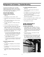
Figure 4.0 - Thermostat Inside

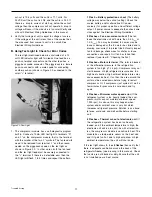
Figure 5.0 -Thermostat Resistor

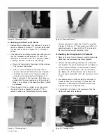
Figure 6.0 - Compressor Pins

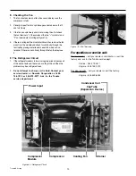
Figure 3.0 - Thermostat Circuit

C. Checking the Thermostat Circuit

1. Remove brown & blue wires from terminal “C” and from

resistor connected to terminal “T”. Connect meter leads
to these wires as shown in Figure 3.0 - no polarity is
needed.

2. If the thermostat is working correctly and calling for cool

then the ohmmeter should read zero (0) ohms (the
thermostat must not be in the “OFF” position). If there is
a reading other than zero then do the following:

a. Rotate the thermostat to the coldest setting and see

if that corrects the problem.

b. If there is still no continuity at the wires then un-

screw and remove the thermostat control inside the
unit. Check that wires are not loose and check for
continuity on the thermostat itself (Figure 4.0). If
there is continuity at the thermostat, then there is a
problem with the wires leading back to the module. If
there is no continuity at the thermostat then it should
be replaced.

3. If there appears to be no problem above then check

the resistor that is connected to terminal “T”. This
resistor is used to set the compressor motor speed.

Connect ohmmeter to either end of resistor assembly
(Figure 5.0). This is a 277-ohm resistor, verify that it is
operating properly to spec (with the 277-ohm resistor,
the control circuit current should be 4mA).

D. Checking the Compressor for Problems

1. Remove all wires from compressor module (make note

where they are connected, see wiring diagram).

2. Unscrew the one mounting screw from the module and

twist module to the rear to disconnect it from compressor.

3. The compressor windings can be checked for defects

by measuring the resistances on the current lead-in
pins (Figure 6.0). If the measured values between all
pins are approximately the same, the compressor motor
is OK.

4. Also check each pin (motor winding) for continuity to

ground. If there is any continuity to ground then the
compressor is internally shorted and will need to be
replaced. This is not a field operation.

5. If a problem is not found in the compressor then the

module will need to be replaced.

Содержание tundra

Страница 1: ...Refrigerators Freezers Tundra Technical Manual Service Training Revised 10 22 03 L 2120 ...

Страница 2: ... Electrical Wiring Guidelines Direct Current 6 DC Wiring Diagram 6 Refrigerators Freezers Operation Temperature Control 7 Rotary Thermostat Knob Control 7 Loading the Appliance 8 Refrigerators Freezers Maintenance Defrosting 9 Cleaning 9 Cleaning the Exterior 9 Cleaning the Interior 9 Cleaning the Condenser 9 Refrigerators Freezers Trouble Shooting GeneralTrouble Shooting 10 Specific Trouble Shoot...

Страница 3: ...o allow compressor oils to settle NOTE Though we state on our packaging to always keep unit upright we cannot control how the carrier handles our boxes This also applies if unit has been set on its side to affix the bottom flange piece Carefully review all wiring diagrams included If you purchase a DC onlyTundra Unit simply wire your unit directly to the appropriate DC power source If you purchase...

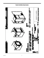
Страница 4: ...4 Installation Tundra Ventilation Requirements ...

Страница 5: ...ailure fan overload and electronic unit overheating as well as destructive battery discharge When an overload protection is activated the compressor enters a cycle in which it makes start attempts at approximately 60 second intervals until a successful start is achieved Overload Protections The compressor overload and start protection cuts off power to the compressor if the compressor speed drops ...

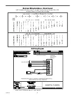
Страница 6: ...18 T22 Models use a 277 ohm resistor Electrical Wiring Guidelines Direct Current ABYC Guideline E9 below meets or exceeds Trucking Industry Standard SAE J1292 Conductor Sizes for 3 Percent Drop in Voltage DC Wiring Diagram ...

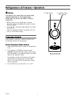
Страница 7: ... Temperature Control Each appliance is fitted with a manual thermostat which automatically maintains set temperatures Rotary Thermostat Knob Control 1 Select desired temperature by means of the adjustment knob 2 The refrigerator is STARTED by turning the knob clockwise Temperature setting range is shown using a band that thickens in the clockwise direction The thicker the band the colder the setti...

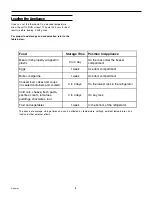
Страница 8: ... day On the rack under the freezer compartment Eggs 1 week Use door compartment Butter margarine 1 week Use door compartment Cooked food cakes and soups in sealed containers and cooled 3 to 4 days On the lowest rack in the refrigerator Cold cuts cheese fresh pasta pastries cream tomatoes puddings chocolates lard 3 to 4 days On any rack Fruit and vegetables 1 week In the bottom of the refrigerator ...

Страница 9: ...ntire interior surfaces and then turn the appliance ON Cleaning Before cleaning disconnect the appliance from the power supply If necessary remove the plug from the power socket Cleaning the Exterior Clean the exterior with warm and then with cold water Dry with a soft cloth Avoid use of abrasive products Cleaning the Interior Remove racks containers and ice trays Clean the interior using warm wat...

Страница 10: ...r contact points and the battery is properly main tained B Excessive Appliance Noise Check that 1 The appliance and refrigerating unit are positioned on flat surfaces 2 The appliance is not touching other objects that may cause vibration 3 The refrigerant lines at the back of the unit if appli cable are not touching or vibrating against the appli ance C Insufficient Refrigerating Capacity Check th...

Страница 11: ...ck wire sizes against the Electrical Wiring Guidelines 2 Flashes Fan over current cut out The fan loads the electronic unit with more than 0 5 A avg or 1 0 A peak Fan may be blocked fan wires may be loose or damaged or the fan motor has failed and is drawing over current to protect itself Visually inspect fan for blockage check wires for chafes or loose connections and repair Or if fan has failed ...

Страница 12: ...ontinuity at the thermostat then it should be replaced 3 If there appears to be no problem above then check the resistor that is connected to terminal T This resistor is used to set the compressor motor speed Connect ohmmeter to either end of resistor assembly Figure 5 0 This is a 277 ohm resistor verify that it is operating properly to spec with the 277 ohm resistor the control circuit current sh...

Страница 13: ... fan then replace it F The Refrigerant Circuit 1 If the refrigerator seems to be running properly and passes all of the above tests and there is no cooling in the unit then the problem may be a refrigerant leak 2 Do not attempt to charge unit in field Contact your service dealer or Dometic Corporation at 804 746 1313 or 954 973 2477 Ask for the Tundra service department Figure 7 0 Fan Terminals Fo...

Страница 14: ... are designed to move air through a heat exchanger by a blower or propeller fan This design necessarily produces a suction on one side of the air handling component and a pressure on the other side Air handling components must be installed so that the suction pressure action does not 1 pressurize an area to the extent that structural failure occurs which could cause harm to occupants or bystanders...

Страница 15: ...Notes ...

Страница 16: ...3227 0699USA 804 746 1313 Facsimile 804 746 7248 www tundra cc 2000N AndrewsAve Ext PompanoBeach FL33069 1497USA 954 973 2477 Facsimile 954 979 4414 FleetsIndustrialEstate 26WillisWay Poole DorsetBH153SU England 44 0 8703306101 Facsimile 44 0 8703306102 ...

Отзывы: