INTRODUCTION
Smart Touch Cabin Control Installation & Operations Manual
2
L-3380 ENGLISH
D
ESCRIPTION
OF
C
ONTROL
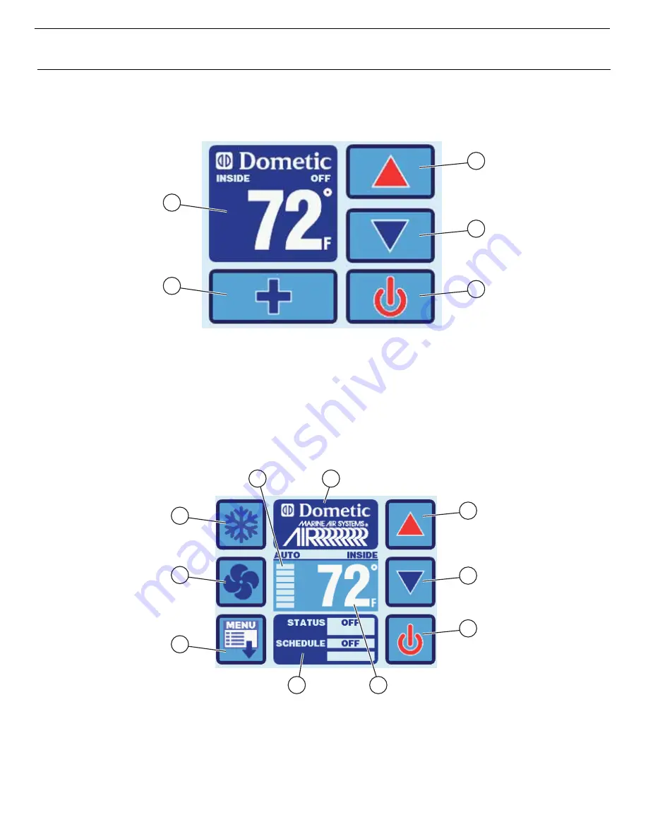
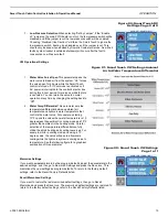
See Figures 1, 2 to identify Home and Main screen displays.
Figure 1: Smart Touch Home Screen
Smart Touch Home Screen Display Layout
1.
Temperature Indicator icon (Inside, set point, outside, and water temperatures)
2.
Up icon - Raise temperature set point
3.
Down icon - Lower temperature set point
4.
Main Screen icon
5.
Power icon
Figure 2: Smart Touch Main Screen
Smart Touch Main Screen Display Layout
1
4
2
3
5
1
5
2
3
7
10
6
9
4
8
1.
Mode Selection icon
2.
Home Screen icon
3.
Up icon - Raise temperature set point
4.
Fan Mode Selection icon
5.
Fan Mode Indicator (Auto, high, medium, low)
6.
Temperature Indicator (Inside, Set Point, Outside, and Water)
7.
Down icon - Lower temperature set point
8.
Menu icon
9.
Status & Schedule icon
10. Power icon


