background image

12

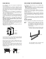
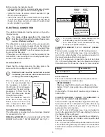
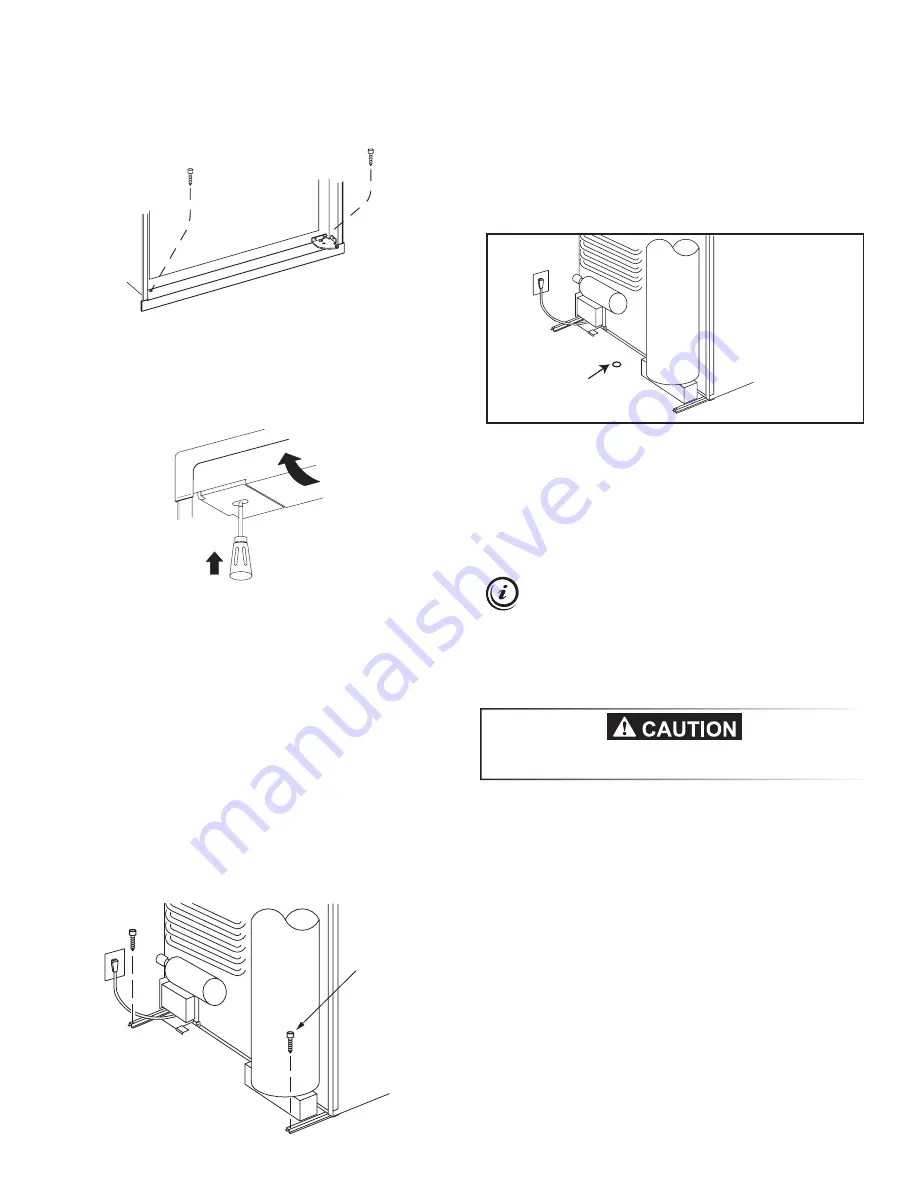
2.  Install two screws in the top frame.

a) Remove the top decoration panel. Open 

the door and gently push the tabs out of the 

hole  in  the  hinge  with  a  flat  blade  screw

-

driver, (both sides), see Fig. 10.

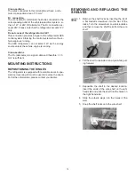
DRAIN WATER HOSE

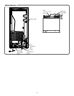
A hole must be drilled through flooring, see Fig. 12.  

The installer has to make sure that the hose does not 

kink when run through the floor. Seal around the hose that 

goes through the drilled hole. 

If a longer hose than supplied is required to get the water 

to drain outside of the vehicle, the installer will have to 

supply the extra length of hose.

Fig. 9

1

2

Fig. 10

Fig. 11

Hole for drain water hose

Fig. 12

RM4605

RM4805

b) Carefully tilt the top decoration panel and 

lift up to remove from top frame. Be careful 

not to damage the circuit  board and wires.

c) Install the two screws in the top frame. (The 

holes are accessible from underneath.)

d) Seal the opening for the screws with alumi-

num tape.

e) Replace the top decoration panel. Be care-

ful not to pinch the wires behind the pan-

el. Make sure the tabs snap back into the 

holes in the hinge plate.

3.  Install one screw in the rear base, see Fig. 

11. The screw shown on the burner side is an 

option. It is not required to properly secure the 

refrigerator in the enclosure.

CONNECTIONS

LP GAS CONNECTION

The refrigerator is designed for operation on Propane 

(Propane only Australia) and LP gas (LP gas New Zea-

land).  

Alternative gas types must not be used to op

-

erate this appliance!


The gas supply system must incorporate an approved gas 

pressure regulator to maintain a supply pressure of 2.75 

kPa. The test point pressure must be 2.70 kPa. Check 

that this is stated on the data plate. 

The gas installation and servicing must be carried out by 

an authorized person and conform to gas fitting regula

-

tions.

The appliance shall be installed in accordance with AS 

5601- Gas Installations. 

The gas supply pipe should be connected to the gas inlet 

connection at the rear of the refrigerator by means of a 

suitable threaded coupling. 

The connection nipple is furnished with an ISO 7/1 - Rp 

1/8 internal pipe thread connection. 

In making the connection to the refrigerator, a un-

ion gas cock of an approved type bottled gas must 

be incorporated in the supply line in a position that 

is readily accessible to the user. For eventual servic-

ing purposes, the union should be on the outlet side 

of the cock and the pipe work should be positioned so 

as not to prevent the refrigerator from being readily  

withdrawn. 

b) Secure the refrigerator and the lower front 

strip with two screws: One screw through 

the hinge, and on the opposite side and 

then, one screw through the lower front 

strip, see Fig. 9.

Optional

Check that the gas supplied to the refrigerator is at the 

correct pressure.

Содержание RM4805

Страница 1: ...mable vapors and liquids in the vicinity of this or any other appliance Improper installation adjustment alteration service or maintenance can cause injury or property damage Refer to this manual For...

Страница 2: ...ns TRANSIT DAMAGE Before you install your refrigerator ensure to remove all protective packaging Check for any damage or marks Transit damage must be reported to whoever is responsi ble for delivery n...

Страница 3: ...LACING THE BULB 7 HEATING CABLE 7 TURNING OFF THE REFRIGERATOR 7 PRODUCT CARE SOME USEFUL HINTS 7 TROUBLESHOOTING 7 MAINTENANCE 7 SERVICE AND SPARE PARTS 8 INSTALLATION INSTRUCTIONS_____________ 8 GEN...

Страница 4: ...ps 1 Turn off the refrigerator Press the ON OFF 1 to OFF 2 Check that there is enough gas in the gas bot tle that its valve is open and that any valves in the gas line to the refrigerator are open 3 T...

Страница 5: ...sources of energy FOOD STORAGE Always keep food in closed containers Never put hot food in the refrigerator allow it to cool first The frozen food compartment is intended for the storage of frozen fo...

Страница 6: ...nd then reset to the desired setting 7 Place the food items back inside CLEANING THE REFRIGERATOR Clean the inside of the refrigerator regularly to keep it fresh and hygienic Never use detergents scou...

Страница 7: ...nsure that the instructions in this manual have been followed Check to make sure that the refrigerator is not tilted ex cessively Verify that the LEDs on the control panel are lit when the ON OFF butt...

Страница 8: ...CE AND SPARE PARTS Service and spare parts are obtainable from your dealer or Dometic consult the telephone directory INSTALLATION INSTRUC TIONS GENERAL INFORMATION The refrigerator is intended for in...

Страница 9: ...rator Fig 5 RM4605 RM4805 G K K L Fig 4 RM4605 RM4805 OVERALL DIMENSIONS Height mm 1385 1544 Width mm 632 632 Depth incl cooling unit mm 627 627 RECESS DIMENSIONS Height mm 1365 1522 Width mm 602 602...

Страница 10: ...10 RM4605 RM4805 12V DC Electrical connection point Gas connection point Gas pressure test point Flue outlet Electrical connection point Gas c o n n e c t i o n point 83 7 95 3 325 4...

Страница 11: ...penings are covered by the vehicle s entrance door when this is set open This would reduce the venti lation airflow to the cooling unit and reduce refrigeration performance The refrigerator has to be...

Страница 12: ...The refrigerator is designed for operation on Propane Propane only Australia and LP gas LP gas New Zea land Alternative gas types must not be used to op erate this appliance The gas supply system mus...

Страница 13: ...ecured so that they cannot come into contact with hot or sharp parts of the refrigerator The free length of the cord is 1 m It is recommended that the receptacle is located on the left side of the ref...

Страница 14: ...The D alternator is a signal cable and therefore 1 1 5 mm2 is sufficient MOUNTING INSTRUCTIONS REPOSITIONING THE HINGES The refrigerator is equipped with reversible doors A spe cial door reversing ki...

Страница 15: ...G R E E N Y E L L O W P T E R M I N A L B L O C K 3 M 4 P 3 2 9 3 0 H 8 6 T 8 5 8 7 7 7 9 9 P 2 1 5 10 3 2 1 P 1 5 P 1 2 P 1 6 P 1 3 7 3 F BATT HEATER LAMP FLAME D GROUND GROUND MAINS HEATER AC HEATER...

Страница 16: ...ding to Low Voltage Directive IP 20 Waiting time TW 8 s Safety time TS 45 s Inter waiting time TWI 120 s Working temperature 20 C to 45 C Nominal working voltage 12 13 8V DC Resistance to vibration ac...

Отзывы: