7
EN
Manual Refrigerator Troubleshooting
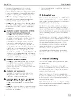
4.2 Component Locations
Figure 1 shows the general component locations. Actual
model component locations may vary.
t
w
e
q
a
r
s
u
y
i
o
t
1
Component Locations
q
Flue Baffle
u
Switch (AC)
w
Cooling Unit
i
Thermostat Piezo
e
Electrode
o
Thermocouple
r
Heating Element
a
Gas Valve
t
Burner Assembly
s
Thermostat
y
Switch (DC)
4.3 Terminology
Term
Definition
2-Way
A refrigerator designed to work on either
LP gas or 120 VAC
3-Way
A refrigerator designed to work on LP
gas, 12 VDC, or 120 VAC
Baffle Box
A box created to meet ventilation
clearances at the rear of the refrigerator
Baffle
Extension
A "false wall" extending off of a box baffle
to ensure strong air to the condensing
fins
Burner Tube
A tube welded to the burner that
conducts heat during gas operation to
provide proper heat exchange to the
cooling unit
Cooling Unit
A sealed ammonia-based absorption
cooling system
Electrode
Passes the spark from the piezo through
the high tension wire to the burner where
the spark ignites the LP gas
Flue Baffle
Installed within the burner tube to slow
heat rise and spread heat along the
burner tube
Gas Valve
Controls LP gas flow and the temperature
of the refrigerator during gas operation
Heating
Element
Provides a specific amount of BTUs of
heat to the burner for electric operation
Piezo
A manual spark generator
Thermocouple
A flame detection device that uses
resistance to keep fuel flowing for gas
operation
Thermostat
Controls the temperature of the
refrigerator during electric operation
Ventilator Fan
Fan positioned in the rear of the
refrigerator to circulate air and help the
cooling unit function properly

