background image

9

START UP INSTRUCTIONS

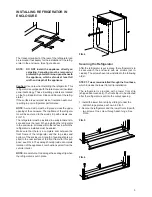
A. A continuous 12 volt DC supply must be available for

the electronic control to function.

B. Press the main power ON/OFF button (1) to the

DOWN position.

C. Press the TEMPERATURE SELECTOR button (2)

until the lamp at the desired setting is illuminated.

Note: Depending on ambient temperature, if the set-
ting is left on in “COLDEST” position too long it may
cause overfreezing.

TO SHUT OFF THE REFRIGERATOR

To shut off the refrigerator press the main power ON/
OFF button (1) to the UP (OFF) position.
This shuts off all DC power to the refrigerator, including
the interior light.

DISPLAY PANEL

A

B

AC

ON

OFF

COLDEST

1

2

3

4

5

1

2

DESCRIPTION OF OPERATING
MODES

LIMP MODE OF OPERATION

This control system contains a feature where it will con-
tinue to operate the cooling system in the event of a fail-
ure of a major operating component. Two different modes
of operation can occur in this category.

If for some reason the display module becomes non func-
tional, the refrigerator will continue to operate and the
temperature of the refrigerator will be maintained at the
MID position within normal temperature tolerances. The
power module will continually attempt to reestablish op-
eration of the display module.

The second limp mode of operation will execute when a
failure of the temperature sensing device or associated
electronic circuitry occurs. If this should occur, the re-
frigerator will run continuously.
The refrigerator will continue to operate in this mode in-
definitely or until a new sensor is installed and the sys-
tem is reset.

Содержание NDE1402

Страница 1: ...of this or any other appliance WARNING Improper installation adjustment alteration service or maintenance can cause injury or property damage Refer to this manual For assistance or additional informa...

Страница 2: ......

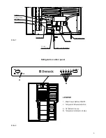
Страница 3: ...A B LEGEND 1 Main Power Button ON OFF 2 Temperature Selector Button A AC Indicator Lamp B Temperature Indicator Lamps 12V DC Thermofuse Heaters Power module and fuses Protection cover 12 Volt Termina...

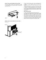
Страница 4: ...kits is provided with proper size openings The flow of ventilating air must not be obstructed The lower side vent is fitted with a panel which provides an adequate access opening for ready serviceabi...

Страница 5: ...which extends at least full width and depth of the appliance Caution Use care when installing the refrigerator This refrigerator is equipped with the latest vacuum insulated panel technology These ins...

Страница 6: ...l become trapped in this space making the top of the refrigerator hot and reduce the efficiency of the refrigerator Drain water hose A hole must be drilled through flooring see FIG 8 The hole must be...

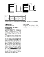
Страница 7: ...denser coil at the back of the refrigerator VENTILATION HEIGHTS CLEARANCES Minimum clearances in inches to combustible materials are G Top 0 K Side 0 L Bottom 0 M Rear 0 N See NOTE Clearance N below N...

Страница 8: ...hydrogen and ammonia gas or in severe cases completely block it resulting in a loss of cooling Any time the vehicle is parked for several hours with the refrigerator operating the vehicle should be le...

Страница 9: ...P MODE OF OPERATION This control system contains a feature where it will con tinue to operate the cooling system in the event of a fail ure of a major operating component Two different modes of operat...

Страница 10: ...getables may be stored in any part of the compartment This compartment is not designed for deep or quick freezing of food Meat or fish whether raw or prepared can be stored in the frozen food storage...

Страница 11: ...refrigerator to the enclosure and slide the refrigerator out of the com partment When replacing the refrigerator make sure that the sealing strips are properly positioned Replacement is the reverse of...

Страница 12: ...t ments and unfavorable installation conditions Contact service point or distributor service dept for assistance CAUTION Turn off the refrigerator before replacing the lamp Wear gloves as protection a...

Страница 13: ...used parts which should be available if required from your Dometic Ser vice Center Part No Description 17 37 72 01 3 Heater 120V 420W 2x 60V 210W 385 04 52 01 6 Lamp cover 385 04 55 01 9 Halogen lamp...

Страница 14: ...e of the shelf will come loose Lower the right hand side of the wire shelf and let the left hand side slide out of the holes in the wall Slide the plastic plugs into the holes of the wall Snap the she...

Страница 15: ...15...

Страница 16: ...16 MO FO 0324...

Отзывы: