3931184/2009.02/G - The right to make technical changes reserved!
5
Doepke
Engli
s
h
1- Table of Contents
Operating Instructions
DBM 1 Proximity Detector
9. General Information
The DBM 1 is a component of the Dupline installation system and is designed to detect,
via the Dupline bus, the movement of people inside rooms. It is therefore suitable e.g.
for lighting control purposes.
The integrated, passive infrared sensor detects any temperature changes in the moni-
tored area between 0.5 and 5 pulses/s. It has a range of up to 10 m and a scanning an-
gle of 90º. If the DBM 1 senses a movement, it activates the configured Dupline
channel.
Because the DBM 1 is supplied by the Dupline signal it does not require an external
power supply.
10. Important Notes in Advance
• The installation may only be carried out by an authorised technician
• This device is suitable exclusively for operating through the signal conductors of the
Dupline bus system, which have been installed in accordance with the requirements
for protective low voltage (see VDE 0100, Part 410, or EN 50090-9-1). Other signal
voltages - even if extensive protective measures are taken - may lead to irreparable
damage to the device as well as danger to people. For further guidelines refer to the
Dupline Planning Aid.
11. Coding
With the DHK 1 hand encoder each channel can, via the modular socket
on the front
of the DBM 1, be assigned any address between A1 and P8. The allocation of channels
is as follows:
Channels which are not required should remain uncoded. Encoding the DBM 1 requires
neither a supply voltage nor the Dupline signal. Although the coding is permanently re-
tained, it may always be overwritten.
12. Installation
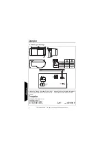
Follow the connection diagram when installing. The DBM 1 may only be mounted in-
doors. All lines to be connected must be dead. The Dupline signal con should
be connected to the „D+“ terminal, and the Dupline signal conductor - to the „D-“ termi-
nal (
).
Channel
Description
Channel
Description
1
Movement signal
5
Control signal for LED
2
Permanent signal
3/4/6..8
Not assigned.


